S.A. Reddi, Deputy Managing Director (Retd), Gammon India Ltd.
India is witnessing construction of very interesting projects in all sectors of Infrastructure. High rise structures, under construction, include residential/commercial blocks up to a height of 320 m and RC chimneys for thermal power stations extending upwards up to 275m. Majority of the structures are in structural concrete. The functional demands of such high rise structures include the use of durable materials. High Strength Concrete, Self–compacting Concrete are gaining widespread acceptance. Apart from the basic structural materials, modern projects require a variety of secondary materials for a variety of purposes such as construction chemicals, waterproofing materials, durability aids etc. The paper highlights some of the recent developments.
Durable ConcreteConcrete Design and Construction Practices today are strength driven. Concrete grades up to M80 are now being used for highrise buildings in India. However, due to escalation in the repair and replacement costs, more attention is now being paid to durability issues. There are compelling reasons why the concrete construction practice during the next decades should be driven by durability in addition to strength.
A large number of flyovers and some elevated roads extending up to 20km in length are being realized in different parts of the country and involve huge outlay of public money. However, the concrete durability is suspect. Many of the structures built during the period from 1970 have suffered premature deterioration. Concrete bridge decks built during the period now require extensive repairs and renovations, costing more than the original cost of the project. Multi-storied buildings in urban areas require major repairs every 20 years, involving guniting, shotcreting etc.
A holistic view needs to be taken about concrete durability. In this context, there are a large number of materials in the market which facilitate durable construction. Apart from the materials, the construction processes have also undergone changes with a view to improving the durability of the finished structure.
High Performance Concrete

In the United States, in response to widespread cracking of concrete bridge decks, the construction process moved towards the use of High Performance Concrete (HPC) mixes. Four types of HPC were developed1:
Very High Early Strength Concrete – 17.5 mPa in 6 hours
High Early Strength Concrete – 42.5 mPa in 24 hours
A Very High Strength – 86 mPa in 28 days
High Early Strength with Fiber Reinforcement
High Performance Concrete was introduced in India initially for the reconstruction of the pre-stressed concrete dome of the Kaiga Atomic Power Project, followed for parts of the Reactors at Tarapur and Rajasthan. Subsequently, a number of bridges and flyovers have introduced HPC up to M75 grade in different parts of India.
Self–compacting Concrete (SCC)SCC was developed by the Japanese initially as a Quality Assurance measure, but now is being widely used for concrete structures worldwide. In India, one of the earliest uses of SCC was for some components of structures at Kaiga Atomic Power Project. Many components of the structures were very heavily reinforced and the field engineers found it difficult to place and compact normal concrete without honeycombs and weaker concrete. SCC was successfully used.
SCC leaving the batching plant is in a semi-fluid state and is placed into the formwork without the use of vibrators. Due to its fluidity, SCC is able to find its way into the formwork and in between the reinforcement and gets self-compacted in the process. SCC is particularly useful for components of structures which are heavily reinforced. The fluidity is realized by modifying the normal mix components. In addition to cement, coarse and fine aggregates, water, special new generation polymer based admixtures are used to increase the fluidity of the concrete without increasing the water content.
Due to its high fluidity, the traditional method of measuring workability by slump does not work. The fluidity is such that any concrete fed to the slump cone falls flat on raising the slump cone; the diameter of the spread of concrete is measured as an indication of workability of SCC. This is called Slump Flow and is in the range of 600 – 800 mm.
Apart from the use of superior grade chemical admixtures, the physical composition of the concrete for SCC has undergone changes. The concrete is required to have more of fine aggregates and compulsorily any of the mineral admixtures – fly ash, ground granulated blast furnace slag (GGBFS), silica fume, metakaolin, rice husk ash etc. Fly ash is abundantly available as a waste product at all the thermal power stations and the Government has encouraged use of fly ash by offering them practically free at the thermal power stations. GGBFS is again a by-product of the steel mills. During the production of steel, a molten steel is poured from blast furnaces and travels in special channels, leaving the impurities on top of the stream. The waste material, being lighter moves on top and easily diverted away from the usable steel.
The diverted slag is quenched and forms small nodules. These nodules are crushed and granulated into very fine product, with particle size smaller than that of cement. The product is marketed in 50 kg bags and available economically in the regions around steel mills with blast furnaces. In other regions, additional transport cost of this bulk material is involved but its use is justified because of contribution to durability of concrete. For the concrete components of the structure for Bandra and Worli sewage outfalls in Mumbai, the German prime contractor insisted on compulsory use of GGBFS for the M40 concrete in order to improve the durability of concrete. GGBFS had to be transported from Vizag in the eastern part of India, in spite of heavy transportation cost. Since then GGBFS is finding widespread use in different parts of India for ensuring durable concrete.
The Use of Mineral Admixtures

After realization of the need for durable concrete structures, the composition of concrete has undergone changes. From being a product made of three or four materials (cement, aggregates, water), today a typical durable concrete consists of six or more materials. The use of low water cement ratio enables a reduction in the volume and size of capillary voids in concrete; this alone is not sufficient to reduce the cement based content of concrete which is the source of micro-cracking from thermal shrinkage and drying shrinkage.
To reduce the cement based content, both the water content and cement content must be reduced as much as possible. Concrete mixes with fewer micro cracks can be produced by blending the cement with mineral admixtures either in the batching plant or in the cement plant. This enhances the service life of concrete structures in a cost-effective manner.
Fly AshThermal power stations are left with an undesirable by-product, fly ash, in large quantities which is not able to effectively utilize or dispose of. Currently, (2009) more than 120 million tonne of fly ash are generated annually and the storage and disposal has been costing the power stations substantial unproductive expenditure. Unfortunately, all the fly ash available at the power stations is not fit for use as mineral admixture directly. Fly ash as a mineral admixture should conform to IS: 3812. Such a material is available in the finer streams of Electro Static Precipitators fitted to the power generation system.
The coarser materials are required to be processed (generally with the help of Cyclones) before being considered for use as mineral admixture for concrete. There are only a few processing units in India, including the one as Nashik Thermal Power Station. As per the Euro Code for Concrete, only processed fly ash can be permitted as mineral admixture in concrete. The code limits the use of fly ash. About 35% of cement may be replaced by fly ash; the actual percentage replacement depending on the outcome of trial mixes.
High Volume Fly Ash Concrete (HVFA)The high volume fly ash concrete (HVFA) represents an emerging technology for highly durable and resource efficient concrete structures. Laboratory and field experience have shown that fly ash from modern coal-fired thermal power plants, when used in large volume (typically 50 - 60% by mass of the total cementitious materials content, is able to impart excellent workability in fresh concrete at a water content that is 15 – 20% less than without fly ash. To obtain adequate strength at early age, further reductions in the mixing water content can be achieved with better aggregate grading and use of super-plasticizers.
HVFA concrete has now been successfully used in a few sporadic projects in India. All SCC in India use HVFA, to the extent of 50% cement replacement. Some concrete roads being built by NHAI have also used HVFA concrete, including the Four-Laning of Satara – Kolhapur National Highway.
Ground Granulated Blast Furnace Slag (GGBFS)The problems associated with the quality of fly ash do not exist in the case of Ground Granulated Blast Furnace Slag GGBFS, as the produce is necessarily the outcome of grinding to the required particle size. Thus the use of GGBFS as a mineral admixture should be preferred, despite long leads for end users in certain parts of India far from the steel plants. GGBFS sold in India is of uniform quality and particle size gradation. For many landmark structures such as the Burj Dubai (the tallest building in the world in 2009) GGBFS has been extensively used as a mineral admixture, even though the material is imported from other countries, resulting in the landed cost being more than that of cement. This was a conscious decision with a view to obtaining a more durable concrete structure.
In India the use of GGBFS has been fairly limited, in spite of all the technical advantages. The Indian Concrete Code permits up to 70% of cement replacement where GGBFS is used. Technically, the use of GGBFS is more effective only at replacement levels of 50% or more. For a number of structures in a port in Andhra Pradesh, typically the M40 concrete mix contained 100 kg of cement and 300 kg of GGBFS.
Portland Slag Cement (PSC) is also available and useful for ensuring durability of concrete structures. Due to the proximity to steel mills, PSC is generally produced in locations close to steel plants. Here again due to the bulky nature of the product, the transportation cost predominate. Another issue concerning quality of the PSC is the actual percentage replacement while making PSC; this information is not normally displayed on the bags, leaving the user at a disadvantage. In developed countries, information regarding the percentage of slag utilized in making PSC is generally printed on each bag of cement.
Condensed Silica Fume (CSF)

CSF is a by-product of Ferro-Silicon industry and at present an imported product, easily available in the Indian market. The particle size is very small, about 100 times smaller than that of cement. It can occupy the voids in between cement particles in a concrete mix, reduce the water demand and thus contribute to a very dense concrete of high durability. Normally, 5 - 10% of cement can be replaced by CSF in order to produce durable concrete. The product is expensive and is used in developed countries only for very high strength concrete (above 75 mPa). Indiscriminate use of CSF for lower grades, barring exceptions, only increases the project cost without corresponding technical benefits. Even when used, the percentage replacement should be based on trial mixes in each case, which may vary from one to 10%. CSF may also be used for High Performance Concrete of lower grades.
Ternary BlendsTernary blends of mineral admixtures are now recommended for improving the durability of important concrete structures. An outstanding example is the Reconstruction of the New I-35 W St. Anthony Falls Bridge crossing the Mississippi River in Minneapolis, US. The new bridge has been opened to traffic in September 2008, less than 14 months after the collapse. HPC has been used for reconstruction with a target 100 year life span. High Performance Concrete containing silica fume and fly ash was used for low permeability.
Two gleaming white concrete sculptures tower 9 m high at each end of the bridge. The sculptures were pre-cast using an SCC mix that included photo-catalytic cement with self cleaning and pollution reducing characteristics. The photo-catalytic cement is one of the new developments in the construction materials industry. The SCC concrete resulted in a marble-like, smooth white finish to the concrete surface. With a low water cementitious material ratio (w/cm), air entrainment and a rapid chloride permeability test (RCPT) value of less than 1500 coulombs at 28 days, the monument will also be a durable feature in the severe environment adjacent to the I-35 W Roadway.2
For the drilled shaft foundations of the I-35 Bridge, SCC was used. To control temperature during curing, fly ash and slag were incorporated as the majority of the cementitious material. This reduced the heat of hydration by approximately 50%. The concrete mixes for the footings and piers were proportioned for mass concrete and durability through the use of fly ash and slag. As the components were massive in size, concrete mixes were modified by cementitious materials, chilled water and cooled aggregates, use of form insulation and internal cooling pipes.
Cement SilosThe use of batching plants for producing concrete is gaining increasing acceptance. As large volumes of cement are used in a batching plant, the cement is generally stored in vertical steel silos. When cement is received in bulkers from the factory, the same is directly pneumatically pumped into the silos which have capacities ranging from 50 to 500 tonne depending upon the project requirements. If only bagged cement is available, they are emptied into the silos, usually with the help of screw conveyors. For modern applications, more than one silo will be required depending on the types of cement and mineral admixture used in the concrete mix.
In a recently commissioned batching plant complex in the Middle East, each of the two plants feature nine cement silos for Portland cement, slag cement, micro silica, fly ash and SRC cement.
Durability Enhancing ProductsA full line of products are available to prevent or repair corrosion damage. A typical corrosion inhibiting admixture prevents deleterious expansion and cracking caused by the formation of rust during over-induced corrosion. There are also penetrating sealants to protect new and repaired concrete from the corrosive effects of chloride. The silane and siloxane based reacting sealers soak into the surface, creating a barrier against water or chlorides.
A number of concrete waterproofing admixtures eliminate the need for conventional external waterproofing membranes and saves time, money and hassle at the construction site. It transforms concrete into a water-resistant barrier by becoming an integral part of the concrete matrix.
Hydrophobic Concrete Waterproofing SystemA typical patented product uses three materials to achieve a water-tight concrete structure, a super-plasticizer which reduces batching water requirements, thus limiting the volume of the capillary pour network in the concrete; a reactive hydrophobic pour blocking concrete admixture and product specific water stop protection at construction dams.
Other accessory products include an operation retardant, curing compound, water stops and polypropylene fiber reinforcement. The patented product is typically added while concrete mix is being prepared to assist waterproofing. One product is applied at the rate of 5 liter per of concrete. Typically the manufacturer provides a warranty period of 10 years. The performance warranty provides for repairing water leakage through industry accepted and approved means for a period of 10 years. The product however has some negative impact on the rate of gain of strength of concrete. As a rough indication, the specified characteristic 28-day strength of concrete will not be achieved at 28 days but at 56 days or more.
The cementitious content of concrete using the integral waterproofing compound shall not be less than 325 k g / c u m with up to 50% fly ash or slag replacement. The water cement ratio shall be adjusted to compensate for the water in the waterproofing compound and super-plasticizer and maintain the required workability. The water cement ratio shall not exceed 0.42. The product is of American origin, represented by an Indian company which provides the necessary technical expertise.
Reinforcement

The revised BIS Code 1786 provides for four grades of reinforcement characterized by the yield strength – Fe 415, Fe 500, Fe 550 and Fe 600. Each of the first three grades is also available with superior ductile properties and a nomenclature is Fe 415D, Fe500D and Fe550D. Primarily the ductile grades specify a higher elongation value. Use of higher grades reduces the tonnage of steel in compression members e.g. columns substantially, results in decongested reinforcement and facilitates easy placement and vibration of concrete. Fe 415 and Fe 500 are easily available in the market. Fe 550 is now being offered by some prime producers–Tata Steel, Sail etc. After the revision of the Code, Fe 550 is also offered in selected diameters.
Fe 500 bars are now used for a number of highrise buildings, bridges and flyovers in India. Lapping of bars results in congestion of steel creates difficulties in proper placement and compaction of concrete and of course more expensive for large diameter bars. Couplers are now preferred instead of lapping. With widespread use, the cost of couplers has come down. The coupler design and manufacture permits the joints in the same plane without the need for staggering as in the case of lapping Fig. 1 shows typical use of couplers for columns of a multi-storied building in Mumbai.
Ternary Blended Cements

Ternary blended cements containing the combination of fly ash–slag, fly ash–silica fume or slag–silica fume are commonly used for concrete in many parts of the world. The European Standard EN 197 for cement lists 27 different combinations for cement. Usually mineral admixture used may present a complimentary effect on cement hydration. Limestone filler addition produces favorable effects on cement test. In particular, the physical effects caused by limestone filler enhance the strength due to hydration acceleration of Portland clinker gains at very early age and the improvement of particle packing of the cementitious system. However, the rate of hydration is initially lower than that corresponding to Portland cement; shows a reduction of strength at early age and similar or greater strength at later ages. Ternary cements containing a limited proportion of limestone filler (no more than 12%) and 20 – 30% GGBFS provide a good resistance to chloride ingress and good performance in sulphate environment of low C3A Portland cement.4
Photo-catalytic CementThis is a patented Portland cement developed by Italcementi Group. The photo-catalytic components use the energy from ultra-violet rays to oxidize most organic and some inorganic compounds. Air pollutants that would normally result in discoloration of exposed surfaces are removed from the atmosphere by the components, and the residues are washed off by rain. This cement can be used to produce concrete and plaster products that save on maintenance cost while they ensure a cleaner environment.3
In addition to Portland cement binders, the product contains photo-catalytic titanium dioxide particles. The cement is already being used for sound barriers, concrete paver blocks and façade elements. Other applications include pre-cast and architectural planners, pavements, concrete masonry units, cement tiles etc.
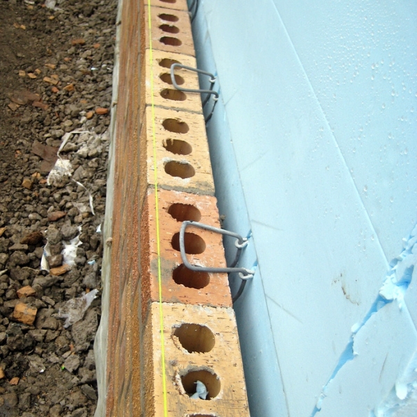
Insulated Concrete Form (ICF)ICF structural elements allow maximum clear spans. The ICF elements are used for large commercial buildings, residential buildings etc.
Exterior Self–leveling Concrete ToppingThis is a Portland cement based product for fast track resurfacing and smoothing of concrete. It produces a smooth flat hard surface and dries quickly without shrinking, cracking or spalling. Pourable or pumpable when mixed with water, it installs 6 to 20 mm thick in one application and up to 50 mm thick with the addition of aggregate. It is pourable or pumpable when mixed with water. It can be used on, above or below grade and it makes spalled or damaged concrete look like new. Once sealed it creates an excellent wearing surface.
Carbon Dioxide (CO2)As part of a future global atmospheric stabilization strategy, industrialized countries may lead to use large amounts of carbon dioxide. CO2 may be used for curing pre-cast concrete units. Manufacturers of concrete masonry units could use CO2 to reduce energy consumption. Steam curing which is conventionally used is energy intensive. Although CO2 curing provides slower strength development than steam curing, the performance can be improved if the blocks are properly pre-conditioned before CO2 curing. It has also been noted that the water absorption of CO2 cured blocks is lower than that of steam cured blocks.
Corrosion Inhibiters for Reinforced Concrete

Calcium nitrate has been proven to inhibit reinforcement corrosion. About 3–4% calcium nitrate of cement by weight is sufficient to protect the reinforcement steel against corrosion. Typically a corrosion inhibiter should
raise the level of chlorides necessary to initiate corrosion or
decrease the rate of corrosion after it has started or
both. Since it does not necessarily prevent corrosion from happening altogether, it is more appropriate to call the product as corrosion retarders.
Coarse Aggregates for ConcreteThe BIS Code (IS:383) permits the use of three types of coarse aggregates–natural gravel (shingle), crushed stone or a blend of both. Many outstanding structures built in India in the past had used river gravel as coarse aggregate for concrete including dams (Bhakra), prestressed concrete aqueducts and siphons (Kunu Siphon), large number of prestressed concrete bridges, power stations (Trombay 500 MW Unit V) etc. The results are excellent. Use of rounded aggregates, by virtue of their geometry, reduces the cement and water content requirements of concrete, thus contributing to the economy. Almost 50% of all the concrete produced in the developed world utilizes natural gravel and broken stone is used only when gravel is not available within economic leads.
Recycled AggregatesWith continuous development activity worldwide, the availability of coarse aggregates from natural sources or crushed rock are dwindling; at the same time, due to demolition of old structures, roads etc., a large amount of debris is generated annually and their disposal poses problems for the individuals and the Governments. In many countries including the UK, any demolition agency is not permitted to dispose of the debris except at predetermined locations which may involve very long leads, expensive operations.
Extensive research has now established that the debris can be crushed, processed and recycled as coarse aggregate for fresh concrete. Such recycling solves the above mentioned problems of disposal, and also more economical. Many national codes in the developed world permit the use of recycled aggregates in concrete, subject to safeguards.
Lightweight AggregatesThese are manufactured products and are extensively used in all types of structures involving longer spans where the dead-load forms a major component of the loads involved in the design. Such lightweight aggregates are manufactured products using expanded clay, sintered fly ash etc. Their contribution to strength depends on the type and quality of the lightweight aggregate, the size fraction used and the amount of aggregate used as well as the type and quality of binder in concrete. However, the addition of lightweight aggregate in concrete reduces the modulus of elasticity.
High Performance Lightweight Concrete

By using high strength/high performance lightweight concrete in prestressed concrete bridge girders, spans of bridge girders can be extended by up to 20%. The implications of using lightweight aggregate on prestressing losses long-term creep and shrinkage deformation should be considered. Compressive strength of up to 75 mPa has been obtained. They also result in reduction in creep and shrinkage and consequently lower prestressed losses. The overall costs for a given load capacity are reduced. The reduction in the structure dead-load leads to a reduction in the foundation size.
Self–curing, Shrinkage-free concreteItalian researchers have produced a concrete by the combined use of
a water reducing admixture based on polycarboxylate in order to reduce both the mixing water and cement.
a shrinkage reducing admixture
an expansive agent based on a special calcium oxide.The combined use of an expansive agent and a PC based water reducing super-plasticizer results in a shrinkage-free concrete even in the absence of any wet curing. Due to the water reduction caused by the PC based super-plasticizer at a given w/c, there is a reduction in the volume of cement paste and a corresponding increase in the amount of aggregates. Both are responsible for significant reduction in the drying shrinkage.
Advanced Composite ReinforcementIn highly corrosive environments, the use of advanced composite fiber reinforced polymers (FRP) is attractive as a replacement for conventional steel reinforcements. While the FRP materials can be resistant to corrosion, there is lack of ductility. At the moment FRP reinforcement in India is quite expensive. The main market for FRP in India is for structural retrofit for increasing the load capacity, to remedy construction defects or repair damages.
Application of Nano TechnologyReducing particle size of a material to nano–scale often imparts new properties or enhances existing ones. This is typical of nano particles of titanium dioxide, which maintains its photocatalytic activity even when mixed with cement. External cement based surfaces become strongly photocatalytic, leading to a much better appearance and a significant reduction in concentration of pollutants in the surrounding air.
The photoactive titanium dioxide was found to be a more powerful photocatalytic agent when its particle size decreased to non size. This makes it a ideal vehicle for application in construction. A cement binder containing about 5% of active titanium dioxide produces concrete with a smooth surface and also converts the pollutants, removes them from the surrounding air. In a typical application on a building in France completed in 2000, the quality of concrete surface have remained unchanged till date. The structure looked as if it were freshly built (Fig 3.)
Cleaner Surfaces and Less PollutionMixing active titanium dioxide with cement produces a binder that maintains its entire normal performance characteristic when used to make concrete. The photocatalytic action makes the surfaces not only to a significant self–cleaning; it also improves the quality of surrounding environment. Using titanium dioxide in glass fiber reinforced concrete offers more efficient and economical way to achieve the benefits of photocatalytics. The environmentally active e-GRC offers the most economical way to achieve cleaner, brighter facades.
Applications for the e-GRC include
Cladding panels and facades elements
Permanent formwork and form liners
Roofing tiles
Motorway and Railway sound barriers
References
Goodspeed, Vanikar & Cook “High Performance Concrete defined for Highway Structures,” Concrete International Vol. 18 No.2, Feb. 1996.
Alan R. Phipps, FIGG Bridge Engineers Inc “HPC for 100 Year Life Span,” HPC Bridge Views, FHWA Issue 52, Nov/Dec 2008.
Concrete that cleans itself and the air,” Concrete International Feb. 2009 Vol. 31 No. 2, The Magazine of the American Concrete Institute.
Irassar et al “Durability of Ternary Blended Cements containing Limestone Filler and GBFS,” ACI Publication SP-234, 2006.
Peter J M Bartos, e-GRC, CONCRETE, UK April 2009


 asd
asd


 Posted in: