Showing posts with label Environmental Engineering. Show all posts

Extruded Polystyrene (XPS): Improved Wall Performance


A building's wall system must constantly fight the invasion of rain, air, vapor and thermal attacks.The wall's ability to provide a barrier to each of these elements relies upon the use of appropriate materials, installed in the correct sequence. There is no such thing as a perfect wall system; however, a wall system that performs with greater efficiency using new efficient materials is achievable.


Steel stud wall construction, even though it is a versatile system, presents a set of challenges that are different from those of wood frame construction. Two major problems exist with steel stud walls that need to be managed: control of moisture and thermal conductivity. As an example of thermal conductivity, steel studs can transfer heat approximately 400 times faster than wood studs. Additionally, when insulation becomes wet, it will decrease the wall system's R-valueas well as contribute to mildew development inside the wall. “R” refers to the resistance to heat flow. As the R-value or RSI number increases, the resistance to thermal transfer becomes greater. RSI is the metric equivalent of the R-value.

Many years of research and study have gone into all the components of a wall system, and this research will continue for years to come. As a result of our better understanding how rain, air, vapor and thermal issues affect a conditioned interior space, many products have been improved upon and new innovations have emerged to provide a more effective wall system. With a finite supply of fossil fuels and greater awareness of energy conservation, the need for a more thermally efficient wall system has become important. As such, a greater emphasis has been placed on the role of insulation and its location within the wall assembly. The need to design energy-efficient buildings that are still economically feasible to construct has become imperative.

Extruded polystyrene insulation, also referred to as XPS, installed as an exterior insulating material and as part of the metal stud wall assembly, has been shown to provide a far more efficient system than fiberglass insulation. Eliminating thermal bridging issues and at the same time resisting moisture, XPS is an ideal solution that should be considered for any metal stud wall system.
Metal Stud Wall System Anatomy

Concrete masonry units (CMU) have long been considered the ideal backup material for brick facing; however, because of increasing installation costs, CMU backup systems have given way to metal stud backup systems. Brick veneer with metal stud backup walls, because they are a very cost effective and versatile wall assembly, are very commonly seen in today’s commercial buildings. The original exterior metal stud wall systems of the 1970’s were simple. They consisted of metal studs at 16 or 24 inches on center, with fiberglass batt insulation having an integral vapor barrier placed in between. Gypsum board sheathing was placed on each side, and 15 pound felt paper was installed over the exterior sheathing. This system eventually would fail and allow air and moisture to enter the building, degrading the insulation and thus the R-Value of the wall, not to mention causing other significant problems.

The Brick Industry Association (BIA) has issued a revised Technical Note #28B that describes in detail Brick Veneer/Steel Stud Wall Construction. The following is an abbreviated summary of their minimum recommendations:
The allowable out-of-plane deflection of the studs due to service level loads should be restricted to L/600 to L/700.
The minimum air space should be increased to 2 inches.
Ties must be spaced closer. There should be one tie for each 2 sq ft (0.18 sq m) of wall area.
Sheathing should be upgraded. Possible choices include: closed-cell rigid insulation meeting ASTM C 578 or C 1289 at a minimum of 1/2" thick; exterior grade gypsum sheathing, OSB or glass fiber mat-faced sheathing or cement board at a minimum of 1/2" thick.
A water-resistant barrier should be installed over sheathing.

Brick veneer with metal stud backup is typically a vented wall system. This is to provide a way out for any moisture that enters the wall system through the brick joints or other openings. A vented cavity also allows for pressure equalization of external pressures caused by wind loads. Venting is accomplished by providing weeps or vents immediately above the wall flashing. Open head joint weeps are recommended with a spacing of no more than 24 inches on center. BIA recommends that wick or tube weeps, when used, be spaced no more than 16 inches on center.

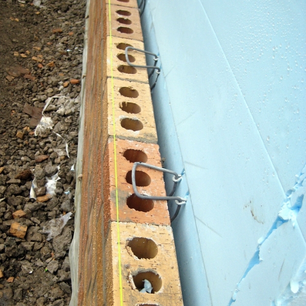
BIA recommends four types of adjustable masonry anchor assemblies for brick veneer/metal stud systems. Each of these is connected to the studs with metal screws. Due to thermal bridging at the stud, condensation can form on the inside face of the stud’s outside flange during long term cold conditions if a thermal break is not provided. When using XPS as part of the exterior system, brick ties that connect directly to the framing must not rely on the compressive resistance of the exterior sheathing material to transfer positive wind loads to the steel studs. This will eliminate the thermal bridge issue at brick ties. All anchors must be embedded at least 1 1/2 inches into the brick veneer with a minimum mortar cover of 5/8 inch to the outside face of the wall.
Improve Wall Performance: Design Options

As long as there is a temperature difference from one side of a wall to the other, heat will transfer from warm to cold. As the thermal resistance in the wall increases, the rate of heat transfer will decrease.

By incorporating a moisture resistant thermal barrier on the exterior side of metal studs, many moisture and thermal issues can be better managed. Extruded polystyrene insulation is specifically designed for wet locations, and yet provides excellent thermal efficiency as a part of the wall assembly. It is the closed-cell structure of the insulation boards that helps resist water and water vapor. For every inch thickness of XPS, an R-Value of 5.0 can be expected. XPS boards come in thicknesses ranging from 1 inch to 3 inches, many with a shiplap edge treatment on the long side. No matter the edge condition, all joints between the insulation boards need to be sealed as recommended by the manufacturer. This is typically done with a butyl type insulation tape.

Detailing and constructing a metal stud cavity wall system using XPS insulation boards can be done in one of three possible ways. In each of these cases, the steel stud wall system is either 4 or 6 inches, with brick veneer and a 2 inch air cavity as the exterior finish system:
Interior and exterior gypsum sheathing on each side. Uninsulated stud cavity. Continuous XPS insulation board over an air barrier membrane covering the exterior sheathing.
Interior gypsum board sheathing only, no exterior sheathing. Uninsulated stud cavity. Continuous air barrier membrane over XPS insulation board attached directly to the metal studs. The steel stud wall assembly will require additional bracing.
Interior and exterior gypsum sheathing on each side. R-11 batt insulation in wall cavity. Continuous XPS insulation board over an air barrier membrane covering the exterior sheathing.
Installation Best Practices

It is critical to install XPS correctly in order for the wall system to function properly. Insulation also provides the necessary comfort for the buildings occupants.

Wherever there is a thermal bridge in the wall system, condensation will occur on the surface where the temperature differences between the interior and exterior are greatest. When fiberglass batt insulation is installed between the metal studs, the exterior flange of the metal stud behind the brick veneer will be exposed to the colder temperatures. The low R-value of exterior sheathing material is not sufficient to eliminate thermal bridging at these locations. In this case, the exterior flange of the metal stud will be subjected to condensation. Brick veneer ties are the weak link, providing a short circuit for thermal bridging. All brick ties are connected to the metal studs by way of metal screws. Approximately two threads of these screws will grip the 16-gauge outer flange of the metal stud. With repeated condensation, rust and corrosion will begin to develop at the juncture between screw and stud. After several years, the brick veneer anchors could begin to fail, resulting in excessive brick movement and cracks forming in the mortar joints. This will allow additional water to infiltrate the building envelope.

A relatively easy solution to this problem is installing a continuous layer of XPS board to the exterior sheathing. When as little as 1 inch of XPS board is installed to the outside face of the exterior sheathing, which also prevents thermal bridging, the temperature at the interior gypsum will increase. A vapor retarder is still required, and in this case it is located between the exterior gypsum board and the XPS. An important step to preventing moisture from forming as condensation in a wall is to keep the wall cavity warm. Thermal bridging will increase the chances of condensation and thus reduce the R-Value of the batt insulation by as much as 50%.
Common Construction Pitfalls

Common pitfalls in designing and installing the thermal barrier include incorrect location and the creation of voids in the thermal barrier. Other problems include installing other materials that create a short-circuit or thermal bridge at the insulation layer.

As an example, if the XPS boards are installed incorrectly, leaving gaps of up to 3/4 inch between uneven edges of the insulation, the overall R-Value of the wall system will drastically be compromised. Tight fitting edges and corners are essential as well. Cut outs for masonry anchors are another problem that needs to be avoided. Correct masonry veneer anchors must be used.
Conclusion

Metal stud backup wall systems offer a cost-effective and rapid way to enclose a building's exterior walls. They are also proving to be reliable alternative to traditional CMU back-up systems. With proper detailing and construction, the metal stud wall can perform successfully for many years. The performance of the building’s wall enclosure depends on the proper installation sequence, clear detailing of each of these barriers, and on the ability to provide proper ventilation of concealed building materials to allow for adequate drying from occasional moisture exposure, without deterioration ormold contamination.

What is Green Roof


What is Green Roof


Green roof refers to a system of roofing that uses plant life for roof covering instead of traditional covering materials. The system of green roofing dates back to the 1960’s but only in recent years it has became a popular alternative to the traditional roofing due to its environmental benefits and savings for heating and cooling. The plants that cover the roof provide an excellent insulation to the building reducing business electricity andbusiness gas consumption significantly but they also act as a natural filter for rainwater which means that they significantly reduce the amount of rain drainage. The plants absorb over 50% of rainwater which would otherwise run into sewage system. The water that is absorbed by the plants on the rooftop then evaporates back into the air. But the benefits of green roof technology do not end in reduction of rainwater.

Green roofing has become increasingly popular in cities because it creates additional green spaces that bring some nature in the concrete and steel jungle. Green roofs in larger buildings often mimic parks and include rich vegetation that does not only provide an additional green space but also attracts wildlife including butterflies, honeybees and other insects as well as birds that can be otherwise rarely seen in urban areas. In addition, green roofs are visually appealing and create an attractive contrast to concrete and steel, while many people take advantage of possibility to grow their own fruits and vegetables as well as flowers on rooftops. Some even have a nice set of teak garden furniture to get the best of the sunshine.

As already mentioned earlier, green roof is covered with plants, most often vegetation that is resistant to weather effects and requires little or no irrigation. Native, hardy, pest- and disease-resistant, and fireproof plants that grow fast and are not invasive are ideal for green roofs. In addition to collecting rainwater, plants on rooftops also absorb the heat which keeps the building warmer during cold winter months, while the growing medium helps keep building cooler during hot summer months. Green roofs have been shown to reduce the costs for cooling and heating for as much as 50 percent offering major financial benefits to building owners. Another major advantage is green roofs over conventional roofing is absorption of air pollutants including carbon dioxide by the plants which helps lower the temperatures in the urban area and reduce the heat island effect.

Green roofs are always created in several layers which besides plants include a growing medium, filter cloth, drainage, insulation as well as waterproof membrane. The construction of a green rooftop as well as selection of plants for roof covering depends on several factors including the size of the building and the type of the roof. Both flat and slopped roofs are appropriate for green roofing but creation of park-like roof systems remains limited to larger buildings as accommodation of large plants and trees is too heavy for houses and medium-sized buildings.
According to plant selection, there are three main green roof types called intensive, semi-intensive and extensive. Intensive green roofs refer to rooftops that accommodate large plants including trees, full lawn, etc. This type of green roofing requires a significant depth of soil as well as lot of maintenance, similar to maintaining a park or large garden. Semi-intensive green roof involves roof covering with plants of moderate size and requires less maintenance. Extensive green roof is the most convenient of all types of green roof systems and involves roof covering with a thin layer of growing medium and vegetation that requires minimal care and maintenance.

Green roof technology is the most environmentally friendly roofing system and has one disadvantage only. The initial costs for green roof are much higher than for traditional roofing due to higher costs for construction works. Despite that it is more cost-efficient than the cheapest roofing systems because green roof technology provides significant savings for heating and cooling. According to some estimations, green roof lowers the costs for heating and cooling for over 50%. In addition, green roof systems are extremely durable. It can last as long as 50 years and requires virtually no repairs like many other roofing systems. Green roofs combined with other green technology such as solar thermal collectors and solar photovoltaic panels can further reduce the costs for heating and cooling as well as help combat the global warming.

Monolithic Emergency Center


Monolithic Emergency Center

David South February 28, 2011, 10:26 a.m. Commercial Monolithic Dome Structures

Emergency Center Prototype A (birds eye view) — This alternative for the Emergency Center has the three domes in a row. It will fit on narrower property. The size of the domes will be determined by what needs to go in the building. (Leland A. Gray Architects, LLC)
The Perfect Emergency Center

A Monolithic Emergency Center is an all-encompassing complex. It includes specific areas for fire engines, rescue vehicles and ambulances; 911 and police communication centers; a disaster shelter.

Ideally, to be effective, such an Emergency Center should beindestructible. It should be impervious to fire, snow, tornadoes, hurricanes and earthquakes. And that’s exactly what a Monolithic Emergency Center is and does.

But what about the doors? Fire stations often have serious problems with their large openings that may compromise a structure’s ability to resist partial or even total destruction.

In 1980, FEMA published the second edition of its Guide 361, Design and Construction Guidance for Community Safe Rooms. For engineers and builders, it delineates what is needed to produce a disaster-safe building. For instance, to be tornado-safe a door must be able to withstand both tremendous pressure and flying projectiles, or it must be protected by a wall designed to withstand such forces.

Monolithic Emergency Centers meet or exceed all of FEMA’s specifications, including their drive-through doors. Those doors have large, curved, protective barriers over them, making them safe.
Location and Use

Their design makes Monolithic Emergency Centers ideal for daily use and in case of disaster. They should be located centrally, manned 24/7 and function as a backstop for smaller, neighborhood, conventional facilities.

Most populated areas have conventional fire stations that serve a specific neighborhood. Conventional stations usually have conventional doors. Those doors and often the entire structures have little if any ability to resist a tornado. Thus the Monolithic Emergency Center should be located centrally, so it’s available to the greatest number of people.
Sizes

We do not have a one-size-fits-all Emergency Center! Instead, we design and build to fit the needs and wants of a community.

Smaller Emergency Centers can be built with only one set of doors. Obviously drivers would have to learn to back around the corner into place. But the facilities would be smaller and less expensive. They can also be designed just as tornado-safe command centers.

Hoover Dame


Hoover Dame


Hoover Dam Details
Hours of operation: Visitors center open daily (except Thanksgiving and Christmas), from 9 a.m. - 6 p.m. (Last ticket sold at 5 p.m.)

Because of heightened security, all vehicles attempting to cross the dam are subject to inspection. Some vehicles -- all trailers, motorhomes and rental trucks -- will be inspected with no exception.

A phone line that details security and road conditions for Hoover Dam is available. Call (888) 248-1259.
Cost: Dam Tour fee: $30 per person. Dam Tour tickets must be purchased in person and are on a first-come first-served basis. Restrictions: No children under the age of 8 and the tour is not accessible to those in wheelchairs or on crutches. Power Plant Tour fee: $11 for adults ages 17-61; $9 for adults 62 and older and active U.S. military personnel (and one adult dependent); $9 for children ages 4-16; children 3 and younger are free. There are no age, height or weight restrictions on the Power Plant Tour. Parking is $7 at the garage across from the visitors center.

Payment options: Cash, Mastercard, Visa, American Express and Discover.
Reservations: Not required.
Location: The Dam is 35 miles south of Las Vegas on U.S. 93. To reach Hoover Dam, take Interstate 15 south to I-215 east. Travel east on I-215 for approximately 10 miles to the junction of I-215 and US 93/ US 95. Take US Highway 93 South and continue about 20 miles to Boulder City. In Boulder City, take a left at the second stoplight in town (there are only 2 of them). Continue on US 93 for about 5 miles (just past the Hacienda Hotel) to the turn-off to Nevada State Route 172 - the Hoover Dam Access Road. Take NV SR 172 for about 2 miles to the Dam on the Nevada/Arizona border.
hoverBridge
Note: Visitors who wish to continue travel into Arizona must re-enter Nevada and access Highway 93 to cross the Hoover Dam Bypass Bridge; the roadway across Hoover Dam is no longer open to through-traffic.
Age/Height/Weight restrictions: Note: The Hoover Dam is open to visitor traffic only.

The Dam Tour has the following restrictions: No children under the age of 8 and the tour is not accessible to those in wheelchairs or on crutches. The Power Plant Tour has no age, height or weight restrictions.

Hoover Dam Review


Named one of the Top 10 Construction Achievements of the 20th Century, Hoover Dam continues to draw crowds more than 70 years after its creation.

Attracting more than a million visitors a year, Hoover Dam is located in Black Canyon, just minutes outside of Las Vegas.

In 1930, construction began on the Hoover Dam, the largest of its kind at the time. Despite the remote location and harsh working conditions, it was completed in less than five years -- two years ahead of schedule -- and well under budget.

The dam is named after America's 31st president, Herbert Hoover, who played a large role in bringing the nearby states into agreement about water allocations, settling a 25-year controversy. The dam has been called Boulder Canyon Dam as well as Boulder Dam, but Hoover Dam was reinstated as the official name by Congress in 1947.

A National Historic Landmark, Hoover Dam is the highest concrete dam in the Western Hemisphere, standing at more than 725 feet above the Colorado River. With 17 generators producing 4 billion kilowatts of electricity a year, it also is one of the country's largest hydroelectric power facilities. Operation and maintenance of the facility are solely supported by revenue from power sales.

Completed in October 2010, the Mike O' Callaghan -- Pat Tillman Memorial Bridge offers spectacular views that were once only available by helicopter. For those who never fully appreciated the dam, it's hard not to become a fan after this. Visitors have access to drive to this bridge and see the dam from a high vantage point. Located about 1,500 feet south of the Hoover Dam, the walkway on the bridge is approximately 900 feet above the Colorado River.

One neat fact is that visitors can go from Nevada to Arizona after crossing the 1,900-foot-long bridge. There are plenty of informative placards before and during the bridge walk. The construction of the bridge came to mind in the 1960s, but didn't actually happen until 40 years later. This bypass was created to not only reduce traffic, but also to protect Lake Mead and the Colorado River from hazardous spills and explosions.

Two tours of the dam are available and well worth the time and money spent. For $11 per person (discounts available for children, seniors and active military) is the Hoover Dam Power Plant Tour. It is broken up into several components at numerous locations. The unique tour format allows guests to pick and choose which locations they want to see and the complete tour generally lasts about two hours. The Hoover Dam Power Plant Tour begins with a brief video show depicting the history of Hoover Dam and how it came to be. Afterwards, a guide will escort you to an elevator for a 500-foot descent to get an up-close look at the power plant generators housed at the base of the dam. Guests will also see the original diversion tunnels and stand atop a giant, 30-foot pipe where they can feel the rumble of Colorado River water racing through it.

Another interesting stop on the tour is an observation deck set above the dam affording panoramic views of the Colorado River and Lake Mead. The location also provides a bird's-eye view of the Hoover Dam facility, including an unobstructed look at the dam's mechanical components.

The tour continues with several stops along the top of the dam, from the Winged Figures of the Republic to the Nevada Intake Tower.

The second tour option is the new Dam Tour. For $30 per person visitors can enjoy all the options of the Power Plant Tour (including access to the visitor's center, observation deck and original Hoover Dam exhibit building), but they will also get to experience a unique and intimate tour of the dam itself.

The tour continues with an unprecedented look inside the dam, entering through the inspection tunnels. Visitors will be able to see inspection markings written on the walls from decades past and then peek out of the vents down onto the river below. After the inspection tunnels, guests will get to go deeper into the dam and see the seepage gallery and a set of antique stairs. This is the ultimate tour for those interested in the Hoover Dam.

The view from the dam also offers a breathtaking look at Lake Mead, the country's largest man-made reservoir. Although water levels have been low recently, Lake Mead can store up to 9.2 trillion gallons of water, equal to two years of the river's annual flow. It also has become a popular recreation area, sought out by more than 9 million visitors each year.

Note: At the Mike O' Callaghan -- Pat Tillman Memorial Bridge, there is limited parking reserved for visiting guests only. Those taking ground transportation tours to the Grand Canyon will be able to cross bridge, but not stop. Depending on the tour vehicle height, guests may not get a view of the Hoover Dam on the way back from the Grand Canyon.

D A M S & RESERVOIRS


D A M S

&

RESERVOIRS


Classification according to type


Earth Dams : 

§ Homogeneous Earth Dams

§ Zoned Earth Dams

§ Diaphragm Dams


Rockfill Dams


Gravity Dams


Arch Dams


Buttress Dams


Classification according to reservoir behind


Flood Control Reservoir


Storage Reservoir


Economic Dam Height


Fish Ways


A Dam:

An obstruction ( عائق) built on a stream or a river to collect water behind it


A Reservoir:

An artificial (صناعي), seasonal or permanent lake, that is created at the US of a dam and used for the purpose of Irrigation, Drinking, Land reclamation, Electricity generation, Fishing, Recreation and (or) Protection of towns from flood danger 


Layout of the Bonneville Dam Site


Layout of the Almendra Arch

Design of Weirs


WEIRS
  
Classification of Weirs:

Design of Weirs:
                    Hydraulic Design
                           Structural Design
                           Floor Design
                           Detailed Drawings
                    Solved Example


Objectives of Weirs in Irrigation Canals

Proper distribution of water carried by a main canal among the branch canals depending upon it
           

Reducing the hydraulic slope (gradient) in a canal (if canal water slope is greater than the allowable water slope)


Reducing head on existing structures

  Collecting sediments at US of structures (sand strap)
 Weirs for reducing water slope in steep lands
Distance between weirs


ac = L * Slope (before)
ab = L * Slope (after)

rise (R)  = ac – ab
                   = L {Slope (before) – slope (after)}

L = distance between weirs
L = R / (natural slope – required slope)


Classification According to Position in Plan


Classification According to Dimensions of Cross Section


Classification According to Position of Down-Stream Water Level
a)    Free- Overfa

Sedimentation Tank Design -Worked-out Examples: Rapid Sand Filter Design


Worked-out Examples:

Population Forecast by Different Methods
Sedimentation Tank Design
Rapid Sand Filter Design
Flow in Pipes of a Distribution Network by Hardy Cross Method
Trickling Filter Design

Population Forecast by Different Methods
Problem: Predict the population for the years 1981, 1991, 1994, and 2001 from the following census figures of a town by different methods.
Year
1901
1911
1921
1931
1941
1951
1961
1971
Population: (thousands)
60
65
63
72
79
89
97
120
Solution:
Year
Population: (thousands)
Increment per Decade
Incremental Increase
Percentage Increment per Decade
1901
60
-
-
-
1911
65
+5
-
(5+60) x100=+8.33
1921
63
-2
-3
(2+65) x100=-3.07
1931
72
+9
+7
(9+63) x100=+14.28
1941
79
+7
-2
(7+72) x100=+9.72
1951
89
+10
+3
(10+79) x100=+12.66
1961
97
+8
-2
(8+89) x100=8.98
1971
120
+23
+15
(23+97) x100=+23.71
Net values
1
+60
+18
+74.61
Averages
-
8.57
3.0
10.66
+=increase; - = decrease
Arithmetical Progression Method:
Pn = P + ni
Average increases per decade = i = 8.57
Population for the years,
1981= population 1971 + ni, here n=1 decade
        = 120 + 8.57 = 128.57
1991= population 1971 +
ni, here n=2 decade
        = 120 + 2 x 8.57 = 137.14
2001= population 1971 + ni, here n=3 decade
        = 120 + 3 x 8.57 = 145.71
1994= population 1991 + (population 2001 - 1991) x 3/10
        = 137.14 + (8.57) x 3/10 = 139.71
Incremental Increase Method:
Population for the years,
1981= population 1971 + average increase per decade + average incremental increase
        = 120 + 8.57 + 3.0 = 131.57
1991= population 1981 + 11.57
        = 131.57 + 11.57 = 143.14
2001= population 1991 + 11.57
        = 143.14 + 11.57 = 154.71
1994= population 1991 + 11.57 x 3/10
        = 143.14 + 3.47 = 146.61
Geometric Progression Method:
Average percentage increase per decade = 10.66
n = P (1+i/100) n
Population for 1981 = Population 1971 x (1+i/100) n
= 120 x (1+10.66/100), i = 10.66, n = 1
= 120 x 110.66/100 132.8
Population for 1991 = Population 1971 x (1+i/100) n
= 120 x (1+10.66/100) 2 , i = 10.66, n = 2
= 120 x 1.2245 146.95
Population for 2001 = Population 1971 x (1+i/100) n
= 120 x (1+10.66/100) 3 , i = 10.66, n = 3
= 120 x 1.355 162.60
Population for 1994 = 146.95 + (15.84 x 3/10) = 151.70


Sedimentation Tank Design
Problem:
 Design a rectangular sedimentation tank to treat 2.4 million litres of raw water per day. The detention period may be assumed to be 3 hours.
Solution: Raw water flow per day is 2.4 x 10⁶ l. Detention period is 3h.

Volume of tank = Flow x Detention perio

Blogroll

 
Design by Wordpress Theme | Bloggerized by Free Blogger Templates | coupon codes