Showing posts with label buildings. Show all posts

What is civil engineering?


"Civil engineering is the art of directing the great sources of power in nature for the use and convenience of mankind"
T. Tredgold, 1828, for the first ICE Royal Charter

Within Northern Ireland civil engineers are responsible for the build and design of most of the things in the built environment, including roads, bridges, canals, hospitals, schools and harbours.


Northern Ireland has a rich history of civil engineering projects. Contemporary civil engineers are working to create infrastructure and projects that will create positive impacts for future generations.

Northern Ireland hosts some of the UK's most impressive civil engineering projects.

The Antrim Coast Road
Perhaps the most famous civil engineering project within Northern Ireland is the Antrim Coast Road.

The project was conceived by the Irish Commissioners of Public Works to open up the Glens of Antrim and give unemployment relief in the days just before the 1845 potato famine.

Their civil engineer was William Bald, who had the vision of building the road along the foot of the cliffs between 1832 and 1842.

The "coast road" as it has become affectionately known, is recognised as one of the most scenic driving routes in the world.

Clearly civil engineers had a major societial impact many years ago, but to illustrate a more modern example of the impact civil engineers have, let's look at a more up to date project:

The Belfast Sewers project
The Belfast Sewers project involved a major upgrade of the Belfast crumbling Victorian sewer network and was completed in 2010.

The Belfast Sewers project was a £160 million project aimed at improving water quality on both the River Lagan and the River Blackstaff while reducing the risk of flooding in the inner city.

The Belfast Sewers received a recent endorsement from BBC's Top Gear programme, with the presenters racing Minis through the dry tunnel.

Life as a civil engineer


Emer Owens has been working within the industry for the past seven years. Emer kindly gives us her perspective on life as a civil engineer:

"I graduated with a MEng in Environmental and Civil Engineering from Queen's University Belfast in 2007.

Since then I have worked as a Design Coordinator with Lagan Construction on DBFO2, the largest roads project within Northern Ireland to date.

Lagan Construction work in Ireland, the UK and internationally across a range of civil engineering projects.

For me, civil engineering is an ideal career due to its varied nature – civil engineers can work indoors or outdoors, and our skills are required in every country around the world.

Often, civil engineers can be overlooked as their expertise is something that can be taken for granted in roads, water supply, buildings and so on. I am currently working towards my professional review with ICE, meaning that I am continually developing and learning so that I can demonstrate my ability as a well rounded engineer.

As a chartered engineer, I will look forward to progressing in such an active industry".


New Construction Materials for Modern Projects


S.A. Reddi, Deputy Managing Director (Retd), Gammon India Ltd.

India is witnessing construction of very interesting projects in all sectors of Infrastructure. High rise structures, under construction, include residential/commercial blocks up to a height of 320 m and RC chimneys for thermal power stations extending upwards up to 275m. Majority of the structures are in structural concrete. The functional demands of such high rise structures include the use of durable materials. High Strength Concrete, Self–compacting Concrete are gaining widespread acceptance. Apart from the basic structural materials, modern projects require a variety of secondary materials for a variety of purposes such as construction chemicals, waterproofing materials, durability aids etc. The paper highlights some of the recent developments.
Durable ConcreteConcrete Design and Construction Practices today are strength driven. Concrete grades up to M80 are now being used for highrise buildings in India. However, due to escalation in the repair and replacement costs, more attention is now being paid to durability issues. There are compelling reasons why the concrete construction practice during the next decades should be driven by durability in addition to strength.

A large number of flyovers and some elevated roads extending up to 20km in length are being realized in different parts of the country and involve huge outlay of public money. However, the concrete durability is suspect. Many of the structures built during the period from 1970 have suffered premature deterioration. Concrete bridge decks built during the period now require extensive repairs and renovations, costing more than the original cost of the project. Multi-storied buildings in urban areas require major repairs every 20 years, involving guniting, shotcreting etc.

A holistic view needs to be taken about concrete durability. In this context, there are a large number of materials in the market which facilitate durable construction. Apart from the materials, the construction processes have also undergone changes with a view to improving the durability of the finished structure.
High Performance Concrete
In the United States, in response to widespread cracking of concrete bridge decks, the construction process moved towards the use of High Performance Concrete (HPC) mixes. Four types of HPC were developed1:
Very High Early Strength Concrete – 17.5 mPa in 6 hours
High Early Strength Concrete – 42.5 mPa in 24 hours
A Very High Strength – 86 mPa in 28 days
High Early Strength with Fiber Reinforcement
High Performance Concrete was introduced in India initially for the reconstruction of the pre-stressed concrete dome of the Kaiga Atomic Power Project, followed for parts of the Reactors at Tarapur and Rajasthan. Subsequently, a number of bridges and flyovers have introduced HPC up to M75 grade in different parts of India.
Self–compacting Concrete (SCC)SCC was developed by the Japanese initially as a Quality Assurance measure, but now is being widely used for concrete structures worldwide. In India, one of the earliest uses of SCC was for some components of structures at Kaiga Atomic Power Project. Many components of the structures were very heavily reinforced and the field engineers found it difficult to place and compact normal concrete without honeycombs and weaker concrete. SCC was successfully used.

SCC leaving the batching plant is in a semi-fluid state and is placed into the formwork without the use of vibrators. Due to its fluidity, SCC is able to find its way into the formwork and in between the reinforcement and gets self-compacted in the process. SCC is particularly useful for components of structures which are heavily reinforced. The fluidity is realized by modifying the normal mix components. In addition to cement, coarse and fine aggregates, water, special new generation polymer based admixtures are used to increase the fluidity of the concrete without increasing the water content.

Due to its high fluidity, the traditional method of measuring workability by slump does not work. The fluidity is such that any concrete fed to the slump cone falls flat on raising the slump cone; the diameter of the spread of concrete is measured as an indication of workability of SCC. This is called Slump Flow and is in the range of 600 – 800 mm.

Apart from the use of superior grade chemical admixtures, the physical composition of the concrete for SCC has undergone changes. The concrete is required to have more of fine aggregates and compulsorily any of the mineral admixtures – fly ash, ground granulated blast furnace slag (GGBFS), silica fume, metakaolin, rice husk ash etc. Fly ash is abundantly available as a waste product at all the thermal power stations and the Government has encouraged use of fly ash by offering them practically free at the thermal power stations. GGBFS is again a by-product of the steel mills. During the production of steel, a molten steel is poured from blast furnaces and travels in special channels, leaving the impurities on top of the stream. The waste material, being lighter moves on top and easily diverted away from the usable steel.

The diverted slag is quenched and forms small nodules. These nodules are crushed and granulated into very fine product, with particle size smaller than that of cement. The product is marketed in 50 kg bags and available economically in the regions around steel mills with blast furnaces. In other regions, additional transport cost of this bulk material is involved but its use is justified because of contribution to durability of concrete. For the concrete components of the structure for Bandra and Worli sewage outfalls in Mumbai, the German prime contractor insisted on compulsory use of GGBFS for the M40 concrete in order to improve the durability of concrete. GGBFS had to be transported from Vizag in the eastern part of India, in spite of heavy transportation cost. Since then GGBFS is finding widespread use in different parts of India for ensuring durable concrete.
The Use of Mineral Admixtures
After realization of the need for durable concrete structures, the composition of concrete has undergone changes. From being a product made of three or four materials (cement, aggregates, water), today a typical durable concrete consists of six or more materials. The use of low water cement ratio enables a reduction in the volume and size of capillary voids in concrete; this alone is not sufficient to reduce the cement based content of concrete which is the source of micro-cracking from thermal shrinkage and drying shrinkage.

To reduce the cement based content, both the water content and cement content must be reduced as much as possible. Concrete mixes with fewer micro cracks can be produced by blending the cement with mineral admixtures either in the batching plant or in the cement plant. This enhances the service life of concrete structures in a cost-effective manner.
Fly AshThermal power stations are left with an undesirable by-product, fly ash, in large quantities which is not able to effectively utilize or dispose of. Currently, (2009) more than 120 million tonne of fly ash are generated annually and the storage and disposal has been costing the power stations substantial unproductive expenditure. Unfortunately, all the fly ash available at the power stations is not fit for use as mineral admixture directly. Fly ash as a mineral admixture should conform to IS: 3812. Such a material is available in the finer streams of Electro Static Precipitators fitted to the power generation system.

The coarser materials are required to be processed (generally with the help of Cyclones) before being considered for use as mineral admixture for concrete. There are only a few processing units in India, including the one as Nashik Thermal Power Station. As per the Euro Code for Concrete, only processed fly ash can be permitted as mineral admixture in concrete. The code limits the use of fly ash. About 35% of cement may be replaced by fly ash; the actual percentage replacement depending on the outcome of trial mixes.
High Volume Fly Ash Concrete (HVFA)The high volume fly ash concrete (HVFA) represents an emerging technology for highly durable and resource efficient concrete structures. Laboratory and field experience have shown that fly ash from modern coal-fired thermal power plants, when used in large volume (typically 50 - 60% by mass of the total cementitious materials content, is able to impart excellent workability in fresh concrete at a water content that is 15 – 20% less than without fly ash. To obtain adequate strength at early age, further reductions in the mixing water content can be achieved with better aggregate grading and use of super-plasticizers.

HVFA concrete has now been successfully used in a few sporadic projects in India. All SCC in India use HVFA, to the extent of 50% cement replacement. Some concrete roads being built by NHAI have also used HVFA concrete, including the Four-Laning of Satara – Kolhapur National Highway.
Ground Granulated Blast Furnace Slag (GGBFS)The problems associated with the quality of fly ash do not exist in the case of Ground Granulated Blast Furnace Slag GGBFS, as the produce is necessarily the outcome of grinding to the required particle size. Thus the use of GGBFS as a mineral admixture should be preferred, despite long leads for end users in certain parts of India far from the steel plants. GGBFS sold in India is of uniform quality and particle size gradation. For many landmark structures such as the Burj Dubai (the tallest building in the world in 2009) GGBFS has been extensively used as a mineral admixture, even though the material is imported from other countries, resulting in the landed cost being more than that of cement. This was a conscious decision with a view to obtaining a more durable concrete structure.

In India the use of GGBFS has been fairly limited, in spite of all the technical advantages. The Indian Concrete Code permits up to 70% of cement replacement where GGBFS is used. Technically, the use of GGBFS is more effective only at replacement levels of 50% or more. For a number of structures in a port in Andhra Pradesh, typically the M40 concrete mix contained 100 kg of cement and 300 kg of GGBFS.

Portland Slag Cement (PSC) is also available and useful for ensuring durability of concrete structures. Due to the proximity to steel mills, PSC is generally produced in locations close to steel plants. Here again due to the bulky nature of the product, the transportation cost predominate. Another issue concerning quality of the PSC is the actual percentage replacement while making PSC; this information is not normally displayed on the bags, leaving the user at a disadvantage. In developed countries, information regarding the percentage of slag utilized in making PSC is generally printed on each bag of cement.
Condensed Silica Fume (CSF)
CSF is a by-product of Ferro-Silicon industry and at present an imported product, easily available in the Indian market. The particle size is very small, about 100 times smaller than that of cement. It can occupy the voids in between cement particles in a concrete mix, reduce the water demand and thus contribute to a very dense concrete of high durability. Normally, 5 - 10% of cement can be replaced by CSF in order to produce durable concrete. The product is expensive and is used in developed countries only for very high strength concrete (above 75 mPa). Indiscriminate use of CSF for lower grades, barring exceptions, only increases the project cost without corresponding technical benefits. Even when used, the percentage replacement should be based on trial mixes in each case, which may vary from one to 10%. CSF may also be used for High Performance Concrete of lower grades.
Ternary BlendsTernary blends of mineral admixtures are now recommended for improving the durability of important concrete structures. An outstanding example is the Reconstruction of the New I-35 W St. Anthony Falls Bridge crossing the Mississippi River in Minneapolis, US. The new bridge has been opened to traffic in September 2008, less than 14 months after the collapse. HPC has been used for reconstruction with a target 100 year life span. High Performance Concrete containing silica fume and fly ash was used for low permeability.

Two gleaming white concrete sculptures tower 9 m high at each end of the bridge. The sculptures were pre-cast using an SCC mix that included photo-catalytic cement with self cleaning and pollution reducing characteristics. The photo-catalytic cement is one of the new developments in the construction materials industry. The SCC concrete resulted in a marble-like, smooth white finish to the concrete surface. With a low water cementitious material ratio (w/cm), air entrainment and a rapid chloride permeability test (RCPT) value of less than 1500 coulombs at 28 days, the monument will also be a durable feature in the severe environment adjacent to the I-35 W Roadway.2

For the drilled shaft foundations of the I-35 Bridge, SCC was used. To control temperature during curing, fly ash and slag were incorporated as the majority of the cementitious material. This reduced the heat of hydration by approximately 50%. The concrete mixes for the footings and piers were proportioned for mass concrete and durability through the use of fly ash and slag. As the components were massive in size, concrete mixes were modified by cementitious materials, chilled water and cooled aggregates, use of form insulation and internal cooling pipes.
Cement SilosThe use of batching plants for producing concrete is gaining increasing acceptance. As large volumes of cement are used in a batching plant, the cement is generally stored in vertical steel silos. When cement is received in bulkers from the factory, the same is directly pneumatically pumped into the silos which have capacities ranging from 50 to 500 tonne depending upon the project requirements. If only bagged cement is available, they are emptied into the silos, usually with the help of screw conveyors. For modern applications, more than one silo will be required depending on the types of cement and mineral admixture used in the concrete mix.

In a recently commissioned batching plant complex in the Middle East, each of the two plants feature nine cement silos for Portland cement, slag cement, micro silica, fly ash and SRC cement.
Durability Enhancing ProductsA full line of products are available to prevent or repair corrosion damage. A typical corrosion inhibiting admixture prevents deleterious expansion and cracking caused by the formation of rust during over-induced corrosion. There are also penetrating sealants to protect new and repaired concrete from the corrosive effects of chloride. The silane and siloxane based reacting sealers soak into the surface, creating a barrier against water or chlorides.

A number of concrete waterproofing admixtures eliminate the need for conventional external waterproofing membranes and saves time, money and hassle at the construction site. It transforms concrete into a water-resistant barrier by becoming an integral part of the concrete matrix.
Hydrophobic Concrete Waterproofing SystemA typical patented product uses three materials to achieve a water-tight concrete structure, a super-plasticizer which reduces batching water requirements, thus limiting the volume of the capillary pour network in the concrete; a reactive hydrophobic pour blocking concrete admixture and product specific water stop protection at construction dams.

Other accessory products include an operation retardant, curing compound, water stops and polypropylene fiber reinforcement. The patented product is typically added while concrete mix is being prepared to assist waterproofing. One product is applied at the rate of 5 liter per of concrete. Typically the manufacturer provides a warranty period of 10 years. The performance warranty provides for repairing water leakage through industry accepted and approved means for a period of 10 years. The product however has some negative impact on the rate of gain of strength of concrete. As a rough indication, the specified characteristic 28-day strength of concrete will not be achieved at 28 days but at 56 days or more.

The cementitious content of concrete using the integral waterproofing compound shall not be less than 325 k g / c u m with up to 50% fly ash or slag replacement. The water cement ratio shall be adjusted to compensate for the water in the waterproofing compound and super-plasticizer and maintain the required workability. The water cement ratio shall not exceed 0.42. The product is of American origin, represented by an Indian company which provides the necessary technical expertise.
Reinforcement
The revised BIS Code 1786 provides for four grades of reinforcement characterized by the yield strength – Fe 415, Fe 500, Fe 550 and Fe 600. Each of the first three grades is also available with superior ductile properties and a nomenclature is Fe 415D, Fe500D and Fe550D. Primarily the ductile grades specify a higher elongation value. Use of higher grades reduces the tonnage of steel in compression members e.g. columns substantially, results in decongested reinforcement and facilitates easy placement and vibration of concrete. Fe 415 and Fe 500 are easily available in the market. Fe 550 is now being offered by some prime producers–Tata Steel, Sail etc. After the revision of the Code, Fe 550 is also offered in selected diameters.

Fe 500 bars are now used for a number of highrise buildings, bridges and flyovers in India. Lapping of bars results in congestion of steel creates difficulties in proper placement and compaction of concrete and of course more expensive for large diameter bars. Couplers are now preferred instead of lapping. With widespread use, the cost of couplers has come down. The coupler design and manufacture permits the joints in the same plane without the need for staggering as in the case of lapping Fig. 1 shows typical use of couplers for columns of a multi-storied building in Mumbai.
Ternary Blended Cements
Ternary blended cements containing the combination of fly ash–slag, fly ash–silica fume or slag–silica fume are commonly used for concrete in many parts of the world. The European Standard EN 197 for cement lists 27 different combinations for cement. Usually mineral admixture used may present a complimentary effect on cement hydration. Limestone filler addition produces favorable effects on cement test. In particular, the physical effects caused by limestone filler enhance the strength due to hydration acceleration of Portland clinker gains at very early age and the improvement of particle packing of the cementitious system. However, the rate of hydration is initially lower than that corresponding to Portland cement; shows a reduction of strength at early age and similar or greater strength at later ages. Ternary cements containing a limited proportion of limestone filler (no more than 12%) and 20 – 30% GGBFS provide a good resistance to chloride ingress and good performance in sulphate environment of low C3A Portland cement.4
Photo-catalytic CementThis is a patented Portland cement developed by Italcementi Group. The photo-catalytic components use the energy from ultra-violet rays to oxidize most organic and some inorganic compounds. Air pollutants that would normally result in discoloration of exposed surfaces are removed from the atmosphere by the components, and the residues are washed off by rain. This cement can be used to produce concrete and plaster products that save on maintenance cost while they ensure a cleaner environment.3

In addition to Portland cement binders, the product contains photo-catalytic titanium dioxide particles. The cement is already being used for sound barriers, concrete paver blocks and façade elements. Other applications include pre-cast and architectural planners, pavements, concrete masonry units, cement tiles etc.
Insulated Concrete Form (ICF)ICF structural elements allow maximum clear spans. The ICF elements are used for large commercial buildings, residential buildings etc.
Exterior Self–leveling Concrete ToppingThis is a Portland cement based product for fast track resurfacing and smoothing of concrete. It produces a smooth flat hard surface and dries quickly without shrinking, cracking or spalling. Pourable or pumpable when mixed with water, it installs 6 to 20 mm thick in one application and up to 50 mm thick with the addition of aggregate. It is pourable or pumpable when mixed with water. It can be used on, above or below grade and it makes spalled or damaged concrete look like new. Once sealed it creates an excellent wearing surface.
Carbon Dioxide (CO2)As part of a future global atmospheric stabilization strategy, industrialized countries may lead to use large amounts of carbon dioxide. CO2 may be used for curing pre-cast concrete units. Manufacturers of concrete masonry units could use CO2 to reduce energy consumption. Steam curing which is conventionally used is energy intensive. Although CO2 curing provides slower strength development than steam curing, the performance can be improved if the blocks are properly pre-conditioned before CO2 curing. It has also been noted that the water absorption of CO2 cured blocks is lower than that of steam cured blocks.
Corrosion Inhibiters for Reinforced Concrete
Calcium nitrate has been proven to inhibit reinforcement corrosion. About 3–4% calcium nitrate of cement by weight is sufficient to protect the reinforcement steel against corrosion. Typically a corrosion inhibiter should
raise the level of chlorides necessary to initiate corrosion or
decrease the rate of corrosion after it has started or
both. Since it does not necessarily prevent corrosion from happening altogether, it is more appropriate to call the product as corrosion retarders.
Coarse Aggregates for ConcreteThe BIS Code (IS:383) permits the use of three types of coarse aggregates–natural gravel (shingle), crushed stone or a blend of both. Many outstanding structures built in India in the past had used river gravel as coarse aggregate for concrete including dams (Bhakra), prestressed concrete aqueducts and siphons (Kunu Siphon), large number of prestressed concrete bridges, power stations (Trombay 500 MW Unit V) etc. The results are excellent. Use of rounded aggregates, by virtue of their geometry, reduces the cement and water content requirements of concrete, thus contributing to the economy. Almost 50% of all the concrete produced in the developed world utilizes natural gravel and broken stone is used only when gravel is not available within economic leads.
Recycled AggregatesWith continuous development activity worldwide, the availability of coarse aggregates from natural sources or crushed rock are dwindling; at the same time, due to demolition of old structures, roads etc., a large amount of debris is generated annually and their disposal poses problems for the individuals and the Governments. In many countries including the UK, any demolition agency is not permitted to dispose of the debris except at predetermined locations which may involve very long leads, expensive operations.

Extensive research has now established that the debris can be crushed, processed and recycled as coarse aggregate for fresh concrete. Such recycling solves the above mentioned problems of disposal, and also more economical. Many national codes in the developed world permit the use of recycled aggregates in concrete, subject to safeguards.
Lightweight AggregatesThese are manufactured products and are extensively used in all types of structures involving longer spans where the dead-load forms a major component of the loads involved in the design. Such lightweight aggregates are manufactured products using expanded clay, sintered fly ash etc. Their contribution to strength depends on the type and quality of the lightweight aggregate, the size fraction used and the amount of aggregate used as well as the type and quality of binder in concrete. However, the addition of lightweight aggregate in concrete reduces the modulus of elasticity.
High Performance Lightweight Concrete
By using high strength/high performance lightweight concrete in prestressed concrete bridge girders, spans of bridge girders can be extended by up to 20%. The implications of using lightweight aggregate on prestressing losses long-term creep and shrinkage deformation should be considered. Compressive strength of up to 75 mPa has been obtained. They also result in reduction in creep and shrinkage and consequently lower prestressed losses. The overall costs for a given load capacity are reduced. The reduction in the structure dead-load leads to a reduction in the foundation size.
Self–curing, Shrinkage-free concreteItalian researchers have produced a concrete by the combined use of
a water reducing admixture based on polycarboxylate in order to reduce both the mixing water and cement.
a shrinkage reducing admixture
an expansive agent based on a special calcium oxide.The combined use of an expansive agent and a PC based water reducing super-plasticizer results in a shrinkage-free concrete even in the absence of any wet curing. Due to the water reduction caused by the PC based super-plasticizer at a given w/c, there is a reduction in the volume of cement paste and a corresponding increase in the amount of aggregates. Both are responsible for significant reduction in the drying shrinkage.
Advanced Composite ReinforcementIn highly corrosive environments, the use of advanced composite fiber reinforced polymers (FRP) is attractive as a replacement for conventional steel reinforcements. While the FRP materials can be resistant to corrosion, there is lack of ductility. At the moment FRP reinforcement in India is quite expensive. The main market for FRP in India is for structural retrofit for increasing the load capacity, to remedy construction defects or repair damages.
Application of Nano TechnologyReducing particle size of a material to nano–scale often imparts new properties or enhances existing ones. This is typical of nano particles of titanium dioxide, which maintains its photocatalytic activity even when mixed with cement. External cement based surfaces become strongly photocatalytic, leading to a much better appearance and a significant reduction in concentration of pollutants in the surrounding air.

The photoactive titanium dioxide was found to be a more powerful photocatalytic agent when its particle size decreased to non size. This makes it a ideal vehicle for application in construction. A cement binder containing about 5% of active titanium dioxide produces concrete with a smooth surface and also converts the pollutants, removes them from the surrounding air. In a typical application on a building in France completed in 2000, the quality of concrete surface have remained unchanged till date. The structure looked as if it were freshly built (Fig 3.)
Cleaner Surfaces and Less PollutionMixing active titanium dioxide with cement produces a binder that maintains its entire normal performance characteristic when used to make concrete. The photocatalytic action makes the surfaces not only to a significant self–cleaning; it also improves the quality of surrounding environment. Using titanium dioxide in glass fiber reinforced concrete offers more efficient and economical way to achieve the benefits of photocatalytics. The environmentally active e-GRC offers the most economical way to achieve cleaner, brighter facades.

Applications for the e-GRC include
Cladding panels and facades elements
Permanent formwork and form liners
Roofing tiles
Motorway and Railway sound barriers
References
Goodspeed, Vanikar & Cook “High Performance Concrete defined for Highway Structures,” Concrete International Vol. 18 No.2, Feb. 1996.
Alan R. Phipps, FIGG Bridge Engineers Inc “HPC for 100 Year Life Span,” HPC Bridge Views, FHWA Issue 52, Nov/Dec 2008.
Concrete that cleans itself and the air,” Concrete International Feb. 2009 Vol. 31 No. 2, The Magazine of the American Concrete Institute.
Irassar et al “Durability of Ternary Blended Cements containing Limestone Filler and GBFS,” ACI Publication SP-234, 2006.
Peter J M Bartos, e-GRC, CONCRETE, UK April 2009


Mitigating Elevator Noise in Multifamily Residential Buildings


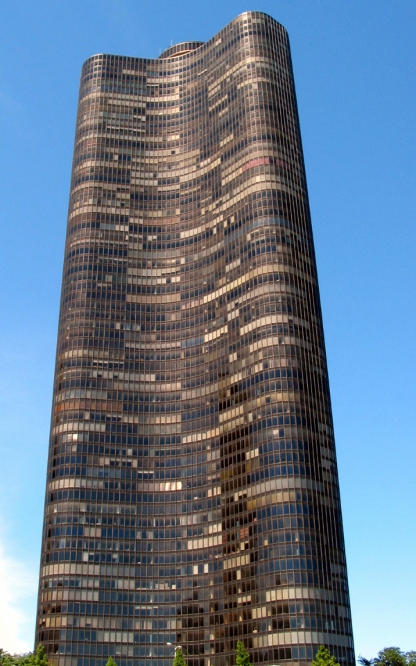
Lake Point Tower, Chicago, IL


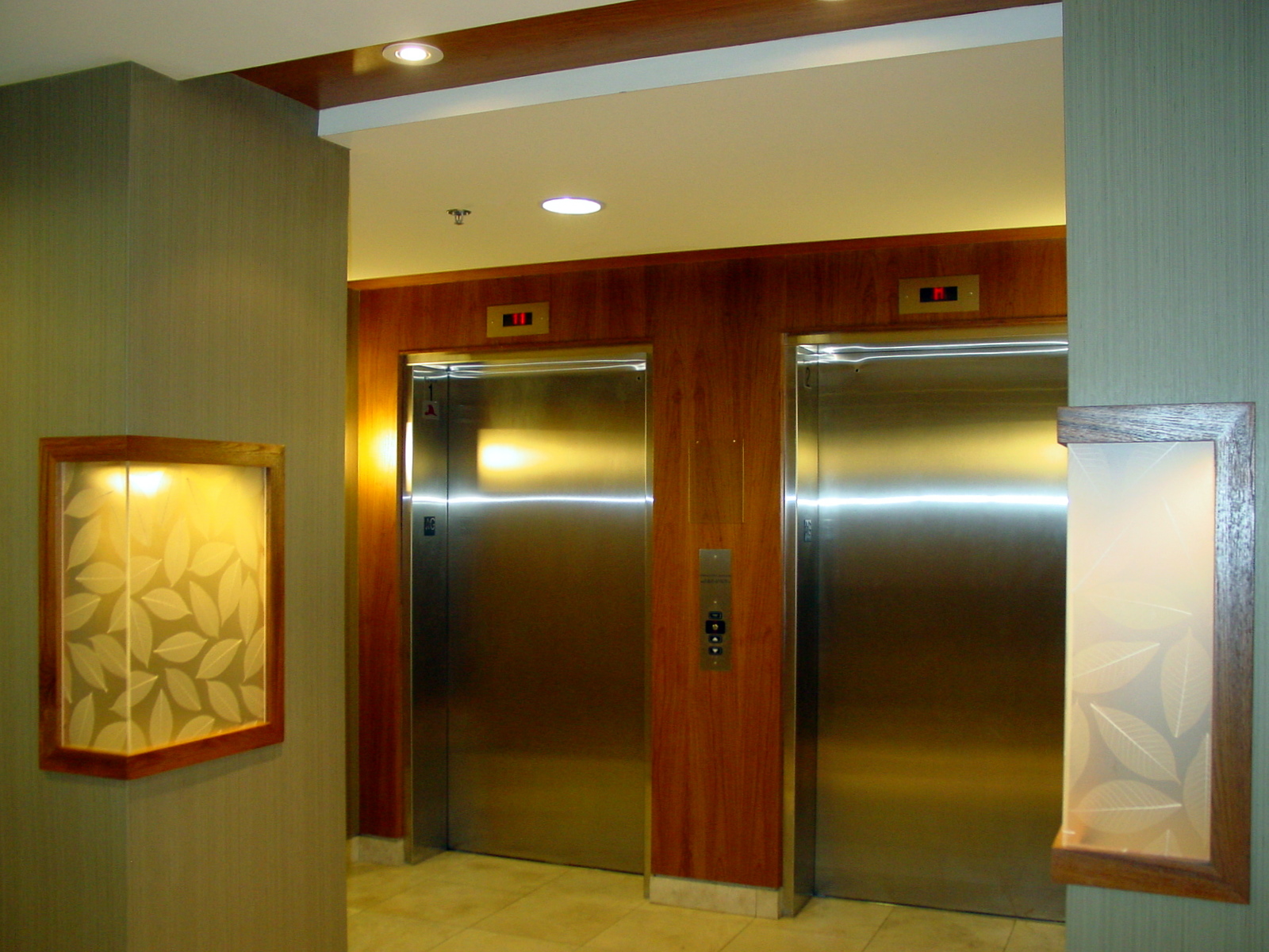
Today’s modern mid rise and high rise luxury condominiums and apartment buildings offer numerous amenities to attract potential owners. They can offer spectacular vistas through floor to ceiling walls of glass, high end finishes on the floor, gourmet style kitchens with all the modern features one could ever want, and a master bedroom suite that offers a tranquil and quiet place to escape. In these building types, elevators become a necessary component for vertical circulation to access the floors. For those residences that are adjacent to the elevator equipment room or the elevator hoistway, the noise and vibration caused by the operation of the elevator can be a potential source of sound intrusion. Because today’s buildings are constructed with lightweight materials, and because there is a need to generate maximum useable square footage, sound transmission issues are compounded. All this combined can result in unsatisfactory living conditions for tens of thousands who live in condominiums or apartments.


The acoustical environment of each residential unit must be taken seriously by both the architect and the developer during the design and planning phase of a project . The operation of elevators will generate significant sound and vibration, which needs to be considered due to the potential impact on adjacent residences. To specifically address these issues related to elevator noise is a challenge. It can be very complicated to identify the source of noise, be it air-borne or structure-borne, after the construction is complete. Many of the impact noises result from structure-borne transmission issues that are not easily calculated or projected prior to the actual construction of each specific project. Additionally, it is difficult for elevator manufacturers to quantitatively produce sound level data for their systems, due to each individual project being uniquely different.

To lessen any future litigation and as part of providing due diligence, it is recommended that a consultant who specializes in architectural acoustics be a part of the design team. An experienced acoustical consultant can provide the architectural team with a number of design options early in the design phase, as well as help explore options to meet the necessary acoustical needs of the facility. Addressing sound isolation and acoustic privacy from mechanical system noise and vibration is a critical part of the final success of the project.
Sound Transmission Class

Sound is the vibrations transmitted through an elastic medium such as a solid, liquid or gas, with frequencies that range from 20 to 20,000 hertz. This is the frequency range which is typically capable of being detected by human ears. Since it requires an elastic medium, sound cannot travel through a vacuum. The more elastic a substance, the better it will conduct sound. An example of this would be comparing lead with steel. Lead is considered inelastic and thus will not conduct sound very well. Steel is considered elastic, making it an exceptional conductor of sound.

A standard by which the construction industry uses building materials for sound attenuation is known as the Sound Transmission Class (STC). The Sound Transmission Class is a number rating of a material or an assembly's ability to resist air-borne sound transfer at frequencies 125-4000 Hz. This range represents the speech frequencies. In general, a higher STC rating will block more noise from transmitting through a partition or assembly. However, STC ratings do not take into account low frequencies below 125 Hz. The ratings are based on laboratory testing and do not take into consideration weak links within the wall assembly such as joints, penetrations and gaps around the perimeter of the wall assembly.

The STC number is derived from sound attenuation values tested at sixteen standard frequencies from 125 Hz to 4000 Hz. These transmission-loss values are then plotted on a sound pressure level graph and the resulting curve is compared to a standard reference contour. Acoustical engineers interpolate these values to determine an STC rating.

Changes in STC with Resulting Changes in Apparent Loudness
STC Rating Change Apparent Loudness Change
+/- 1 Barely Imperceptible
+/- 3 Just Perceptible
+/- 5 Clearly Noticeable
+/- 10 Twice (or half) as Loud


Typical Examples of Sound Levels
Source of Sound Decibel (dB)
Calm Room 20-30
Normal Human Speech 40-60
Moving Car from 30'-0" Away
60-80 

Traffic Noise on a Major Road from 30'-0" Away
80-90 

Typical Jackhammer
100 

Jet Engine from 300'-0" Away
110-140 

Hearing Damage Begins with Short Exposure
120 

Human Threshold of Pain
130 


Another form of sound measure is impact or structure-borne noise known as Impact Insulation Class (IIC). This rates a floor/ceiling assembly’s resistance to the transmission of structure-borne or impact noise. Achieving a higher IIC rating, such as 70, does not always ensure that footfall noise will be totally eliminated. Of all noises, totally eliminating the impact noise of footfall is very difficult.
Sources of Elevator Noise


The air-borne sound and vibration from elevator systems can result from a variety of sources and transmission paths. Several of the more significant sound sources are:
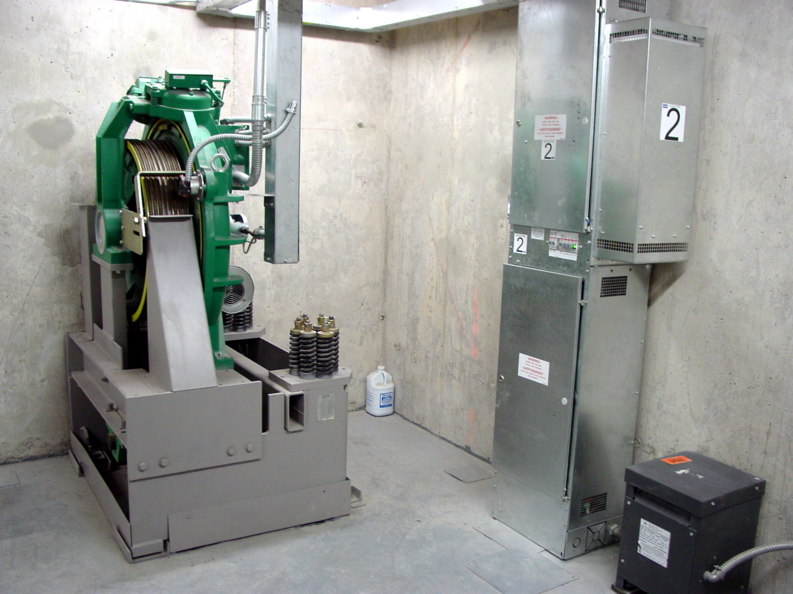
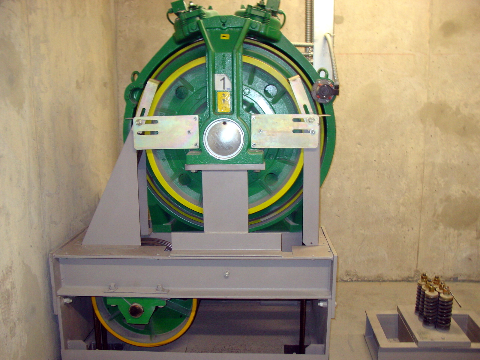
Tonal noise from traction elevator hoist machinery
Tonal noise from switchgear for traction elevators
Hydraulic elevator pumps and machinery
Transient noise from poorly adjusted elevator car guide rollers or bumps in rails
Elevator doors
Door enunciators

Machine-Room-Less Elevators have a drive system that is supported by the rails. Therefore, the vibration generated at the time an elevator runs can easily be transmitted to the hoistway enclosure from the rails. For this reason, architects need to be cautious of generating structure-borne noise by the vibration from the hoistway to adjoining rooms.

Most of the sound energy will be transmitted by the separating wall assembly itself, but there are many opportunities for "flanking paths" or "sound leaks" to occur. Some of the common air-borne sound transmissions through flanking paths in buildings are:
Plenums and suspended ceilings
Ducts with no sound attenuation material
Transoms and air grilles
Unblocked ceiling plenum spaces
Wall perimeters with no acoustical sealant
Ducts, piping, electrical devices and fixtures
Masonry joints

Sound travels not only in a straight path from its source but also bounces off partitions, bends around barriers, and squeezes through small openings, all of which can allow noise to reach surprisingly far beyond its point of origin.
Basic Principles for Controlling Sound

In general, loud speech can be understood fairly well through an STC 30 wall, but should not be audible through an STC 60 wall. An STC of 50 is a common building standard and blocks approximately 50 dB from transmitting through the partition. However, occupants would still be subject to some barely audible sounds of loud speech. Wall assemblies with a higher STC such as 60 would be as much as 10dB better. For particularly sensitive areas where sound transmission is a concern, this higher STC rating should be installed.
A separate wall around the perimeter of the elevator hoist must extend to the structural deck in order to achieve optimal isolation. Walls extending only to a dropped ceiling will result in a flanking path for sound.
Sound will travel through the weakest elements, such as doors, plumbing penetrations or electrical outlets.
When the mass of a barrier is doubled (increasing the STC rating), an increase by approximately 5 dB will be gained. This increase will be clearly noticeable.
Installing insulation within a wall or floor/ceiling cavity will improve the STC rating by about 4-6 dB, which is also noticeable.
Metal studs perform better than wood studs. Staggering the studs or using dual studs can provide a substantial increase in isolation.
Increasing air space in a wall assembly will also improve isolation.

Building codes such as The Uniform Building Code (UBC) and International Building Code (IBC) contain requirements for sound isolation between adjacent dwelling units or between dwelling units and adjacent public areas such as halls, corridors, stairs or service areas. These codes also apply to hotels, motels, apartments, condominiums, monasteries and convents.
Code requirements for walls: STC rating of 50 (if tested in a laboratory) or 45 (if tested in the field).
Code requirements for floor/ceiling assemblies: STC and IIC ratings of 50 (if tested in a laboratory) or 45 (if tested in the field).

An assembly rated at STC 50 will satisfy the building code requirement. However, as mentioned above, occupants could still be subject to awareness, if not understanding, of loud speech. Therefore, it is typically expected that luxury accommodations have a more rigorous design goal. When field testing is done, this evaluates the dwelling's actual construction assembly and includes all sound paths.
Typical STC Ratings for Masonry Walls

STC ratings for masonry and CMU walls are based on the weight of the block. Improved performance can be achieved by filling the cells with additional materials as shown in the chart below.
Estimated STC Ratings for CMU Walls

Wall Thickness, Inches Hollow Units Grout Filled Sand Filled
Weight STC Weight STC Weight STC
4 20 44 38 47 32 46
6 32 46 63 51 50 49
8 42 48 86 55 68 52
10 53 50 109 60 86 55


The STC rating of a CMU wall can be estimated based on its weight using the following formula:
STC = 0.18W + 40

Where W = pounds per square foot (psf)

There are many unique factors that can change the final STC calculations. The estimate could be off by as much as +/- 4 dB. There are numerous other issues that need to be addressed to get a more accurate calculation.
Improving STC Rating of Walls

While the science behind sound is well understood, using that science to create the desired acoustical quality within a building or room is complex. No single acoustical solution can be universally applied to all designs. Each environment features unique parameters that the architect and designer must consider when developing floor plans, selecting materials, and designing assemblies. Virtually every material from furniture and wall and floor coverings to computer equipment will affect sound to some degree. However, designing wall partitions, ceiling systems and floor/ceiling assemblies for the distinct qualities of a space will achieve the most effective sound control.
Adding mass: When the mass of a barrier is doubled, the isolation quality (or STC rating) increases by approximately 5 dB, which is clearly noticeable.
Air space: airspace of 1 ½" will improve the STC by approximately 3 dB. An air space of 3" will improve the STC by approximately 6 dB. An airspace of 6" will improve the STC by approximately 8 dB.
Cavity insulation: installing insulation within a wall or floor/ceiling cavity will improve the STC rating by about 4-6 dB, which is clearly noticeable.
Sound Suppression Guidelines for Noise Reduction
The surrounding walls, floor, and ceiling assembly should have a substantial STC rating. If noise sensitive areas are nearby, STC 50 or 55 at a minimum should be used as the design criteria for the surrounding structure. All cracks and gaps around the perimeter must be filled with the appropriate acoustical caulking.
In situations where noise-sensitive areas are not an issue, two layers of drywall (four total) are still recommended, and the area around the perimeter should be sufficiently caulked. Double-layer drywall with staggered seams works best.
Doors must have a good STC rating. A rated door and frame assembly are needed if a noise-sensitive area is nearby. Ideally an STC 55 door system would be best, to match the walls. Rated doors may have cam hinges that raise the door and then lower it when it closes to eliminate the gap at the base and a tight seal around the perimeter, along with sufficient mass to give the door a good STC rating. Doors with a lower rating, such as STC 40, may be adequate for a non-noise sensitive areas.
If a standard door is used, good sealing hardware is needed to seal around the perimeter of the door.
Penetrations through the equipment room walls must be kept to a minimum. When pipes and conduit pass through the walls, they must be sealed with mortar or the appropriate acoustical sealant to prevent noise leaks. A heavy, solid material must be used. Do not use fiberglass.
If the walls are concrete block, do not paint them. Unpainted block has about 33% absorption, which is lost with a coat of paint. Fiberglass panels on the ceiling or walls covering 25% of the area are beneficial, but not mandatory.
Vibration isolation of the elevator machinery normally will not be needed when the unit is attached to a concrete foundation. If used on elevated floor slabs, 2” deflection springs properly sized and installed are suggested.
Conduit from the power unit to the hoistway should be “vibrationally” isolated from the wall and the perimeter of the pipe should be sealed with the appropriate acoustical sealant to prevent acoustical leaks or flanking paths for vibration noise.

Regardless of the building type, elevators will generate considerable amounts of noise and vibration. In acoustically sensitive spaces, such as residences around the machine room and hoistway, it is important that the design team review all guidelines and criteria carefully. With the input of the elevator manufacturer, the structural engineer and the architect, the sound and vibration from the operation of elevators can be successfully mitigated.

مسجد الشاكرين في مدينة اسطنبول


مسجد الشاكرين في مدينة اسطنبول، وهو أحد أجمل المساجد التي رأيتها على الأطلاق، ويتميز بأنه أول مسجد تقوم بتصميمه امرأة في المدينة.

الصورة ملتقطة بطريقة

ADA 1 - Office Building "An der Alster 1" Hamburg, 2007


ADA 1 - Office Building "An der Alster 1" 

Hamburg, 2007

© J. MAYER H. Architects


Project Team: Juergen Mayer H., Hans Schneider, Wilko Hoffmann, Andre Santer, Sebastian Finckh, Marta Ramírez Iglesias, Georg Schmidthals, Marcus Blum
Competition Team: Juergen Mayer H., Jan-Christoph Stockebrand, Marcus Blum, Klaus Küppers, Hans Schneider

Invited competition 2005, 1st Prize
Project: 2005-2007
Completion: 2007
Client: Cogiton Projekt Alster GmbH, Hamburg

Architect on Site: Imhotep, Donachie und Blomeyer, Berlin with Architekturbuero Franke, Hamburg
Structural Engineers: CBP, Hamburg
Building Services: Energiehaus with Sineplan, Hamburg
Light Engineers: Andres – Lichtplanun, Hamburg
Landscape Architects: Breimann & Bruun, Hamburg
Photographer: Dirk Fellenberg


The building site is situated at the intersection between Hamburg’s lively downtown and its urban landscape that is rich in water and mature trees. It is at the transition from city to nature, and the gateway building to the bustling metropolitan core.

The horizontal striped facade with its floating “eyes” celebrates the view onto this unique context. A public park in front of the building continues the design strategy of the facade into the landscape. The “eyes” in the facade and the platforms in the park enable the places to meet and contemplate.

The office spaces serve both a generic spatial layout and specific moments related to the “eyes”. Large spans provide for various office layout configurations in
combination with balconies and climatically tempered outdoor spaces of the “eyes”. The eyes are just a bigger space inside the double skin facade, which work the same as the whole facade.

This kind of facade highly economizes on energy, because the windows of the inner facade can be used to ventilate. This is the reason why no additional air conditioning is needed for the office building. In Germany, the companies mostly don’t want buildings with air conditioning because of the high running costs. Furthermore an air conditioning is also problematic in terms of health conditions. In addition to that the concrete core activation system inside the concrete ceilings cools the building during summertime and heats it during wintertime with the help of water. The warmed surfaces allow lower heating costs in wintertime and thus save energy.

The office building “An der Alster 1” links its interior and exterior spaces to the public park in front of the building and to the city context of Hamburg, becoming a new anchor at the prestigious Aussenalster waterfront. 

JOH 3 - Residential Building


JOH 3 - Residential Building 

Apartmenthouse Johannisstraße 3
Berlin

© J. MAYER H. Architects
Project Architect: Hans Schneider
Main Facade (Photo: Ludger Paffrath)


Facade (Photo: Patricia Parinejad)


Gardenview (Visualization: Ludger Paffrath)


Apartment (Photo: Ludger Paffrath)


Section (Drawing: J. MAYER H.)


Project Team: Juergen Mayer H., Marcus Blum, Wilko Hoffmann, Filipa Frois Almeida
Competition Team: Juergen Mayer H., Thorsten Blatter, Marcus Blum
Invited competition 2008, 1st Prize
Project: 2008-2012
Completion: Spring 2012
Client: Euroboden Berlin GmbH

Architect on Site: Architekturbuero Wiesler, Stuttgart with Thomas Quinten Projektmanagement, Berlin
Structural Engineers: EiSat GmbH, Berlin
Building Services: Ingenieurgesellschaft Striewisch mbH
Building Physics: Ingenieurbüro Santer, Duisburg
Fire Security Consultant: Fire Safety Consult, Berlin and KLW Ingenieure GmbH, Berlin

Property development group Euroboden is realizing a unique residential building at Johannisstraße in Mitte, Berlin's downtown district. J. MAYER H. architects' design for the building, which will soon neighbour both Museum Island and Friedrichstrasse, reinterprets the classic Berliner residential building with its multi-unit structure and green interior courtyard. The sculptural design of the suspended slat facade draws on the notion of landscape in the city, a quality visible in the graduated courtyard garden and the building's silhouette and layout. Plans for the ground floor facing the street also include a number of commercial spaces. The generously sized apartments will face south-west, opening themselves to a view of the calm, carefully designed courtyard garden. Spacious, breezy transitions to the outside create an open residential experience in the middle of the city that, thanks to the variable heights of the different building levels, also offers an interesting succession of rooms. The units' varying floor plans and layouts indicate a number of housing options; condominiums are organized into townhouses with private gardens, classic apartments or penthouses with a spectacular view of the old Friedrichstadt. The integrated design concept, which incorporates everything from façade to stairwells, elevators to apartment interiors, promises a unique spatial and living experience with an eye to high design.

Balneary Centre


Located amongst the natural salty springs in Persani Village, Romania is the Balneary Centre designed by architects ArchVision Studio. The community was desirous of developing a large scale relaxation, health and rejuvenation facility in this rural area, offering spin off social, economical and cultural development of the whole territory.

ACROS Fukuoka: The Largest “Green Roof” in Japan


ACROS Fukuoka: The Largest “Green Roof” in Japan


We ever discuss issues Green Roof which is currently applied inmany different buildings and houses. And that is also “most” Green Roof.

Building ACROS (Asian Crossroads Over The Sea) in the city of Fukuoka, Japan, the building may be the most environmentally friendly (eco-friendly) in the city (perhaps also in Japan).

That Buildings have a height of about 60 meters and buildings such as in general, which is decorated with glass in front, but the back of a garden that looks green and knowledgeable with the 35,000 plants that also spread to the roof of the building.With the terraced roof design at each level of the roof that have built a beautiful garden.


The goal, of course, to reduce heat in the building so the usage Air Condition (AC) is not too large, and also filter out the dirty air around.

Using Photoshop, Photographer Creates Mind-Boggling Buildings


Using Photoshop, Photographer Creates Mind-Boggling Buildings


Using Photoshop, Spanish photographer Victor Enrich has manipulated his own images of buildings to create surreal structures that border on the whimsical.

Stripping buildings of science and logic, Enrich makes towers unzip, roads go upward, even a “fries” building and other mind-boggling distortions.

Yet, the parallel universe that Enrich has created appears somewhat plausible.

According to Enrich, he tries to inject “realism” into his work, by editing existing, real-world building blocks.

Enrich spends up to a month digitally editing each shot.

“Most architects respect the law ‘form follows function’ … my ‘buildings’ definitely don’t have an architectonic function … but they DO have other functions,” writes Enrich.

One wonders what that might be, perhaps a cultural commentary laced with Enrich’s own sense of humor?


Energy Efficient Buildings: Asia Pacific

ESCO Market Dynamics, Performance Contracting, Energy Efficiency Retrofits, Green Building Certifications, Financing Structures, Market Analysis and Forecasts


Demand for energy in the Asia Pacific region is rising quickly, driven in large part by rapid economic growth in Southeast Asia, India, and China. Simultaneously, Asian governments and industry leaders are highly focused on creating a more sustainable and energy-efficient economy, and these goals have intensified their attention on the building sector, which is one of the primary sources of energy consumption. Driven by these macro trends, energy efficiency solutions for commercial buildings have become an increasingly larger priority for companies within the region.

Energy service companies (ESCOs) in Asia Pacific are meeting demand by providing energy-saving systems and comprehensive services adapted to their customers’ business facilities and building spaces. Over the past several years, performance contracting has become a more and more common business model to assist building owners and managers in optimizing energy use in existing buildings. At the same time, builders within the region have quickly adopted green building certification programs and other tools for improving the efficiency and mitigating the environmental impacts of commercial buildings.

This Pike Research report analyzes market issues and opportunities related to energy efficiency solutions for commercial buildings in the Asia Pacific region. The report examines the role of energy service companies, performance contracting business models, the economics and financing structures behind energy efficiency retrofits, and key green building trends. Market forecasts are provided through 2015, and key industry players are profiled in depth.
Key questions addressed:
Where are the biggest opportunities to save energy in commercial buildings?
How will legislative initiatives affect the market for energy efficient buildings?
Which business models and financing structures are being utilized to pursue energy efficiency within the Asia Pacific region?
What are the primary challenges and opportunities associated with market development?
How do the dynamics of individual country markets differ from one another?
Who are the key industry players to watch in each country?
What is the size of the addressable market for energy efficiency solutions over the next 5 years
Who needs this report?
Energy Service Companies
Commercial building owners
Government agencies
Investment community
Efficient lighting manufacturers and installers
HVAC system installers
Table of Contents
1. Executive Summary
2. Market Issues

2.1 Market Perception

2.1.1 Japan

2.1.2 China

2.1.3 Association of Southeast Asian Nations

2.2 Energy Efficiency Policies in APAC

2.2.1 Australia

2.2.2 Japan

2.2.3 Korea

2.2.4 Singapore

2.2.5 Vietnam

2.2.6 Policy Comparison – China and ASEAN

2.3 Market Barriers in ASEAN and China

2.4 Technologies in APAC

2.4.1 Japan

2.4.2 Australia

2.4.3 Singapore

2.4.4 General Energy Efficiency Measures in ASEAN

2.5 ESPC Business Process in APAC

2.6 ESCO Industry Overview – China

2.6.1 Global Cooperation in ESCO Industry in China

2.6.2 Energy Efficiency Trends in China

2.6.3 Spearhead in China – EMCA

2.6.4 Increasing Market Participants in China

2.6.5 Energy-Saving Services in China

2.6.6 Energy-Saving Results in China

2.6.7 Market Barriers in China

2.6.8 Market Opportunities in China

2.7 ESCO Industry Overview – Japan

2.7.1 Spearhead in Japan – JAESCO

2.7.2 Energy-Saving Services in Japan

2.7.3 ESCO Definition and Services in Japan

2.7.4 Market Activities Offered by Japanese ESCOs in ASEAN

2.8 ESCO Industry Overview – Korea

2.8.1 Spearhead in Korea – KAESCO

2.8.2 Energy Efficiency Services in Korea

2.8.3 Market Growth in Korea

2.9 ESCO Industry Overview – Singapore

2.9.1 Market Competition in Singapore

2.9.2 Systematic Schemes in Singapore

2.9.3 Segmentation and Market Landscape in Singapore

2.10 ESCO Industry Overview – India

2.10.1 Global Cooperation in India

2.10.2 Market Growth in India

2.10.3 Spearhead in India – BEE

2.10.4 Market Barriers in India

2.11 ESCO Industry Overview – Vietnam

2.11.1 Market Outlook in Vietnam

2.11.2 Market Barriers in Vietnam

2.11.3 Training Program in Vietnam

2.12 Financing Schemes for Energy Efficiency Projects in APAC

2.12.1 Japan

2.12.1.1 Japanese ESCO Financing Conditions

2.12.1.2 Japanese ESCO Financing Scopes

2.12.2 Australia

2.12.3 Korea

2.12.4 China

2.12.5 Thailand

2.13 Taxation Programs

2.13.1 Japan

2.13.2 Korea

2.13.3 Thailand

2.14 General Flow of Energy Efficiency Process

2.14.1 Japanese Lifecycle Operating Cost Revaluation

2.14.1 Energy Audit Results: Consumption per Total Floor Area by Sector in Japan

2.14.1 Energy Audit Results Analysis for Japanese Department Stores

2.14.1 Energy Efficiency Program Process in India

2.15 Strategic Suggestion and Market Outlook
3. The Asia Pacific ESCO Industry

3.1 Energy Self-Sufficiency Ratio in APAC

3.2 Japan

3.2.1 Transition of Energy Consumption by Sector

3.2.2 Energy Efficiency Analysis and Retrofit Cases

3.2.3 Energy Efficiency Rate Performed by Retrofit

3.2.4 Energy Consumption in Building by Source

3.2.5 ESPC Segmentation by Market

3.2.6 Per-Floor Energy Consumption in Building Spaces

3.2.7 Japanese ESCO Markets

3.2.7.1 Revenue by Contract Method

3.2.7.2 Project Cases by Contract Method

3.2.7.3 ESCO Project Financial Sources

3.3 Korea

3.3.1 Registered ESCOs and Changes

3.3.2 ESPC Cases and Revenue of ESCOs

3.3.3 ESCO Segmentation by Sector

3.3.4 ESCO Market Segmentation by Technology

3.3.5 ESPC Cases by Company Size

3.3.6 ESPC Revenue by Company Size

3.3.7 Energy-Saving Results with ESCOs

3.4 China

3.4.1 Energy Consumption by Sector

3.4.2 Energy Efficiency Investment and ESCO Revenue

3.4.3 ESCO Contract Methods

3.4.4 ESCO Market Segmentation by Technology

3.5 Australia

3.5.1 Energy Use in Commercial Sector

3.5.2 Australian GHG Emissions in Buildings

3.6 Thailand

3.7 India

3.7.1 ESCO Revenue

3.7.2 ESCO Market Segmentation by Sector

3.7.3 ESCO Market Segmentation by Technology
4. Green Building Certifications

4.1 Introduction

4.2 Green Star and NABERS in Australia

4.3 CASBEE in Japan

4.3.1 CASBEE for Pre-Design (Underdevelopment): CASBEE-PD

4.3.2 CASBEE for New Construction: CABEE-NC

4.3.3 CASBEE for Existing Buildings: CASBEE-EC

4.3.4 CASBEE for Renovation

4.3.5 Scope and Concept of CASBEE

4.4 Certifications in Korea

4.4.1 GBCS in Korea

4.4.2 LEED Activities in Korea

4.5 Certifications in Singapore

4.5.1 EASe in Singapore

4.5.2 Green Mark in Singapore

4.5.3 Energy Smart Buildings in Singapore

4.5.4 Energy Smart Office in Singapore

4.6 HK BEAM in Hong Kong

4.7 Certification Efforts in ASEAN
5. Market Forecasts

5.1 ESCO Revenue in APAC

5.2 ESCO Revenue by Country

5.2.1 China

5.2.2 Japan

5.2.3 Korea

5.2.4 India

5.2.5 Australia

5.2.6 ASEAN
6. Key Industry Players

6.1 ACTSYS

6.2 CPG Facilities Management

6.3 Elyo South East Asia

6.4 Energy Solutions Co. (EnerSol)

6.5 Equation Energy

6.6 ESCO Energy Solutions

6.7 Excellent Energy International

6.8 FESCO

6.9 G-Energy Global

6.10 Hitachi

6.11 Honeywell

6.12 IndoChine Engineering

6.13 Johnson Controls

6.14 Kaer

6.15 LIG Ensulting

6.16 LJ Energy

6.17 NTT Facilities

6.18 PowerU

6.19 Samsung Everland

6.20 Siegle + Epple Asia

6.21 Trane Korea

6.22 UGL Premas

6.23 Yamatake Corp.
7. Company Directory
8. Acronym and Abbreviation List
9. Table of Contents
10. Table of Charts and Figures
11. Scope of Study, Sources and Methodology, Notes
List of Charts and Figures
ESCO Revenue, Asia Pacific: 2009-2015
Number of ESCOs, China: 1998-2006
Energy Efficiency Analysis and Retrofit Cases by Segment, Japan: 1997-2007
Energy Efficiency Rate Performed by Retrofit by Sector, Japan
ESPC Segmentation by Market, Japan: 1997-2007
Energy Efficiency Project Revenue by Contract Methods, Japan: 1998-2007
Energy Efficiency Project Cases by Contract Method, Japan: 1998-2007
ESPC Cases and Revenue, ESCOs, Korea: 1993-2009
ESPC Cases by Company Size, Korea: 1999-2009
ESPC Revenue by Company Size, Korea: 1999-2009
Energy Saving Amount and Tons of Oil Equivalent (TOE), Korea: 1993-2009
Energy Consumption by Sector, China: 2008
Energy Efficiency Investment and ESCO Revenue, China: 2003-2008
Energy Use in the Commercial Sector, Australia
ESCO Revenue, Thailand: 2000-2006
ESCO Market Segmentation by Sector, India
ESCO Market Segmentation by Technology, India
Certified Buildings and Square Meters in Green Mark Scheme, Singapore: 2005-2008
ESCO Revenue, APAC: 2009-2015
ESCO Revenue, Historical Data and Forecast, China: 2005-2015
ESCO Revenue, Historical Data and Forecast, Japan: 2005-2015
ESCO Revenue, Historical Data and Forecast, Korea: 2005-2015
ESCO Revenue, India: 2009-2015
ESCO Revenue, Australia: 2009-2015
ESCO Revenue, ASEAN: 2009-2015
The Process Flow by Energy Savings Contract Methods in APAC
Energy Conservation Facilities Applied to Financing Programs in Japan
Japanese Lifecycle Operating Cost Revaluation
Energy Consumption Rate per Unit Total Floor Area by Sector in Japan
Benchmarking, Energy Audit, and M&V Processes in India
Energy Self-Sufficiency Ratio of Major Countries
Transition of Final Energy Consumption by Sector, Japan: 1973-2006
Energy Consumption Rate in Building Spaces in Japan
Per-Floor Energy Consumption by Sources in Commercial Buildings, Japan: 1973-2007
Financial Sources for Energy Efficiency Projects, Japan: 1998-2007
Number of ESCOs, Korea: 1992 to 2009
ESCO Market Segmentation by Sector, Korea: 1993-2009
ESCO Market Segmentation by Technology, Korea: 1993-2009
ESCO Market Segmentation by Technology, China: 2005
Indian ESCO Market Growth by Revenue and Growth Rate (Year-to-Year): 2003-2007
Sustainability Ranking of Buildings by CASBEE Standard in Japan
Hypothetical Boundary for Building Environment Used in CASBEE Standard in Japan
LEED Certification Candidate Buildings Established in Songdo International Business District in Korea
Service and Equipment Coverage Provided by NTT Facilities in Building Spaces
List of Tables
The State of ESCO Business and Energy Efficiency Policy in ASEAN and China
General Energy Efficiency Measures in ASEAN
Financing Programs for Energy Savings and Retrofits in Japan
ESCO Financing Conditions in Korea

Blogroll

 
Design by Wordpress Theme | Bloggerized by Free Blogger Templates | coupon codes