


 asd
asd

A building's wall system must constantly fight the invasion of rain, air, vapor and thermal attacks.The wall's ability to provide a barrier to each of these elements relies upon the use of appropriate materials, installed in the correct sequence. There is no such thing as a perfect wall system; however, a wall system that performs with greater efficiency using new efficient materials is achievable.
Steel stud wall construction, even though it is a versatile system, presents a set of challenges that are different from those of wood frame construction. Two major problems exist with steel stud walls that need to be managed: control of moisture and thermal conductivity. As an example of thermal conductivity, steel studs can transfer heat approximately 400 times faster than wood studs. Additionally, when insulation becomes wet, it will decrease the wall system's R-valueas well as contribute to mildew development inside the wall. “R” refers to the resistance to heat flow. As the R-value or RSI number increases, the resistance to thermal transfer becomes greater. RSI is the metric equivalent of the R-value.
Many years of research and study have gone into all the components of a wall system, and this research will continue for years to come. As a result of our better understanding how rain, air, vapor and thermal issues affect a conditioned interior space, many products have been improved upon and new innovations have emerged to provide a more effective wall system. With a finite supply of fossil fuels and greater awareness of energy conservation, the need for a more thermally efficient wall system has become important. As such, a greater emphasis has been placed on the role of insulation and its location within the wall assembly. The need to design energy-efficient buildings that are still economically feasible to construct has become imperative.
Extruded polystyrene insulation, also referred to as XPS, installed as an exterior insulating material and as part of the metal stud wall assembly, has been shown to provide a far more efficient system than fiberglass insulation. Eliminating thermal bridging issues and at the same time resisting moisture, XPS is an ideal solution that should be considered for any metal stud wall system.
Metal Stud Wall System Anatomy
Concrete masonry units (CMU) have long been considered the ideal backup material for brick facing; however, because of increasing installation costs, CMU backup systems have given way to metal stud backup systems. Brick veneer with metal stud backup walls, because they are a very cost effective and versatile wall assembly, are very commonly seen in today’s commercial buildings. The original exterior metal stud wall systems of the 1970’s were simple. They consisted of metal studs at 16 or 24 inches on center, with fiberglass batt insulation having an integral vapor barrier placed in between. Gypsum board sheathing was placed on each side, and 15 pound felt paper was installed over the exterior sheathing. This system eventually would fail and allow air and moisture to enter the building, degrading the insulation and thus the R-Value of the wall, not to mention causing other significant problems.
The Brick Industry Association (BIA) has issued a revised Technical Note #28B that describes in detail Brick Veneer/Steel Stud Wall Construction. The following is an abbreviated summary of their minimum recommendations:
The allowable out-of-plane deflection of the studs due to service level loads should be restricted to L/600 to L/700.
The minimum air space should be increased to 2 inches.
Ties must be spaced closer. There should be one tie for each 2 sq ft (0.18 sq m) of wall area.
Sheathing should be upgraded. Possible choices include: closed-cell rigid insulation meeting ASTM C 578 or C 1289 at a minimum of 1/2" thick; exterior grade gypsum sheathing, OSB or glass fiber mat-faced sheathing or cement board at a minimum of 1/2" thick.
A water-resistant barrier should be installed over sheathing.
Brick veneer with metal stud backup is typically a vented wall system. This is to provide a way out for any moisture that enters the wall system through the brick joints or other openings. A vented cavity also allows for pressure equalization of external pressures caused by wind loads. Venting is accomplished by providing weeps or vents immediately above the wall flashing. Open head joint weeps are recommended with a spacing of no more than 24 inches on center. BIA recommends that wick or tube weeps, when used, be spaced no more than 16 inches on center.
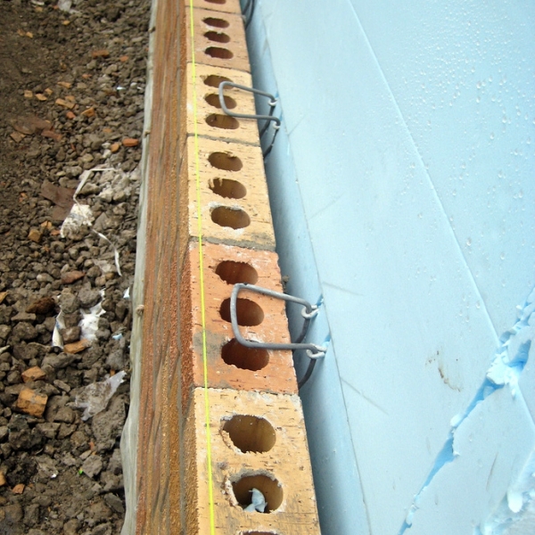
BIA recommends four types of adjustable masonry anchor assemblies for brick veneer/metal stud systems. Each of these is connected to the studs with metal screws. Due to thermal bridging at the stud, condensation can form on the inside face of the stud’s outside flange during long term cold conditions if a thermal break is not provided. When using XPS as part of the exterior system, brick ties that connect directly to the framing must not rely on the compressive resistance of the exterior sheathing material to transfer positive wind loads to the steel studs. This will eliminate the thermal bridge issue at brick ties. All anchors must be embedded at least 1 1/2 inches into the brick veneer with a minimum mortar cover of 5/8 inch to the outside face of the wall.
Improve Wall Performance: Design Options
As long as there is a temperature difference from one side of a wall to the other, heat will transfer from warm to cold. As the thermal resistance in the wall increases, the rate of heat transfer will decrease.
By incorporating a moisture resistant thermal barrier on the exterior side of metal studs, many moisture and thermal issues can be better managed. Extruded polystyrene insulation is specifically designed for wet locations, and yet provides excellent thermal efficiency as a part of the wall assembly. It is the closed-cell structure of the insulation boards that helps resist water and water vapor. For every inch thickness of XPS, an R-Value of 5.0 can be expected. XPS boards come in thicknesses ranging from 1 inch to 3 inches, many with a shiplap edge treatment on the long side. No matter the edge condition, all joints between the insulation boards need to be sealed as recommended by the manufacturer. This is typically done with a butyl type insulation tape.
Detailing and constructing a metal stud cavity wall system using XPS insulation boards can be done in one of three possible ways. In each of these cases, the steel stud wall system is either 4 or 6 inches, with brick veneer and a 2 inch air cavity as the exterior finish system:
Interior and exterior gypsum sheathing on each side. Uninsulated stud cavity. Continuous XPS insulation board over an air barrier membrane covering the exterior sheathing.
Interior gypsum board sheathing only, no exterior sheathing. Uninsulated stud cavity. Continuous air barrier membrane over XPS insulation board attached directly to the metal studs. The steel stud wall assembly will require additional bracing.
Interior and exterior gypsum sheathing on each side. R-11 batt insulation in wall cavity. Continuous XPS insulation board over an air barrier membrane covering the exterior sheathing.
Installation Best Practices
It is critical to install XPS correctly in order for the wall system to function properly. Insulation also provides the necessary comfort for the buildings occupants.
Wherever there is a thermal bridge in the wall system, condensation will occur on the surface where the temperature differences between the interior and exterior are greatest. When fiberglass batt insulation is installed between the metal studs, the exterior flange of the metal stud behind the brick veneer will be exposed to the colder temperatures. The low R-value of exterior sheathing material is not sufficient to eliminate thermal bridging at these locations. In this case, the exterior flange of the metal stud will be subjected to condensation. Brick veneer ties are the weak link, providing a short circuit for thermal bridging. All brick ties are connected to the metal studs by way of metal screws. Approximately two threads of these screws will grip the 16-gauge outer flange of the metal stud. With repeated condensation, rust and corrosion will begin to develop at the juncture between screw and stud. After several years, the brick veneer anchors could begin to fail, resulting in excessive brick movement and cracks forming in the mortar joints. This will allow additional water to infiltrate the building envelope.
A relatively easy solution to this problem is installing a continuous layer of XPS board to the exterior sheathing. When as little as 1 inch of XPS board is installed to the outside face of the exterior sheathing, which also prevents thermal bridging, the temperature at the interior gypsum will increase. A vapor retarder is still required, and in this case it is located between the exterior gypsum board and the XPS. An important step to preventing moisture from forming as condensation in a wall is to keep the wall cavity warm. Thermal bridging will increase the chances of condensation and thus reduce the R-Value of the batt insulation by as much as 50%.
Common Construction Pitfalls
Common pitfalls in designing and installing the thermal barrier include incorrect location and the creation of voids in the thermal barrier. Other problems include installing other materials that create a short-circuit or thermal bridge at the insulation layer.
As an example, if the XPS boards are installed incorrectly, leaving gaps of up to 3/4 inch between uneven edges of the insulation, the overall R-Value of the wall system will drastically be compromised. Tight fitting edges and corners are essential as well. Cut outs for masonry anchors are another problem that needs to be avoided. Correct masonry veneer anchors must be used.
Conclusion
Metal stud backup wall systems offer a cost-effective and rapid way to enclose a building's exterior walls. They are also proving to be reliable alternative to traditional CMU back-up systems. With proper detailing and construction, the metal stud wall can perform successfully for many years. The performance of the building’s wall enclosure depends on the proper installation sequence, clear detailing of each of these barriers, and on the ability to provide proper ventilation of concealed building materials to allow for adequate drying from occasional moisture exposure, without deterioration ormold contamination.
 Posted in:


